32 Product Manual PM WSC/WDC
D
Common
D D D
n
= +
1
2
2
2 2
0 5
....
.
WARNING: The above information is a guide only. Consult local codes and/or latest version of ASHRAE
Standard 15 for sizing data.
Pumpout Units
Although McQuay chillers can pump the entire refrigerant charge into the condenser and valve it off, there are
occasions when pumpout units are required due purely to specification requirements or unusual job
considerations. The McQuay Model LSA units consist of an ASME storage tank, a top mounted air-cooled
condensing unit with a 1 HP compressor to provide motive power, and necessary valves and fittings to
constitute a complete system. Optional casters are available. Storage tank capacities range from 1078 pounds
to 4570 pounds of R-134a. Very large dual compressor units may require an additional storage tank.
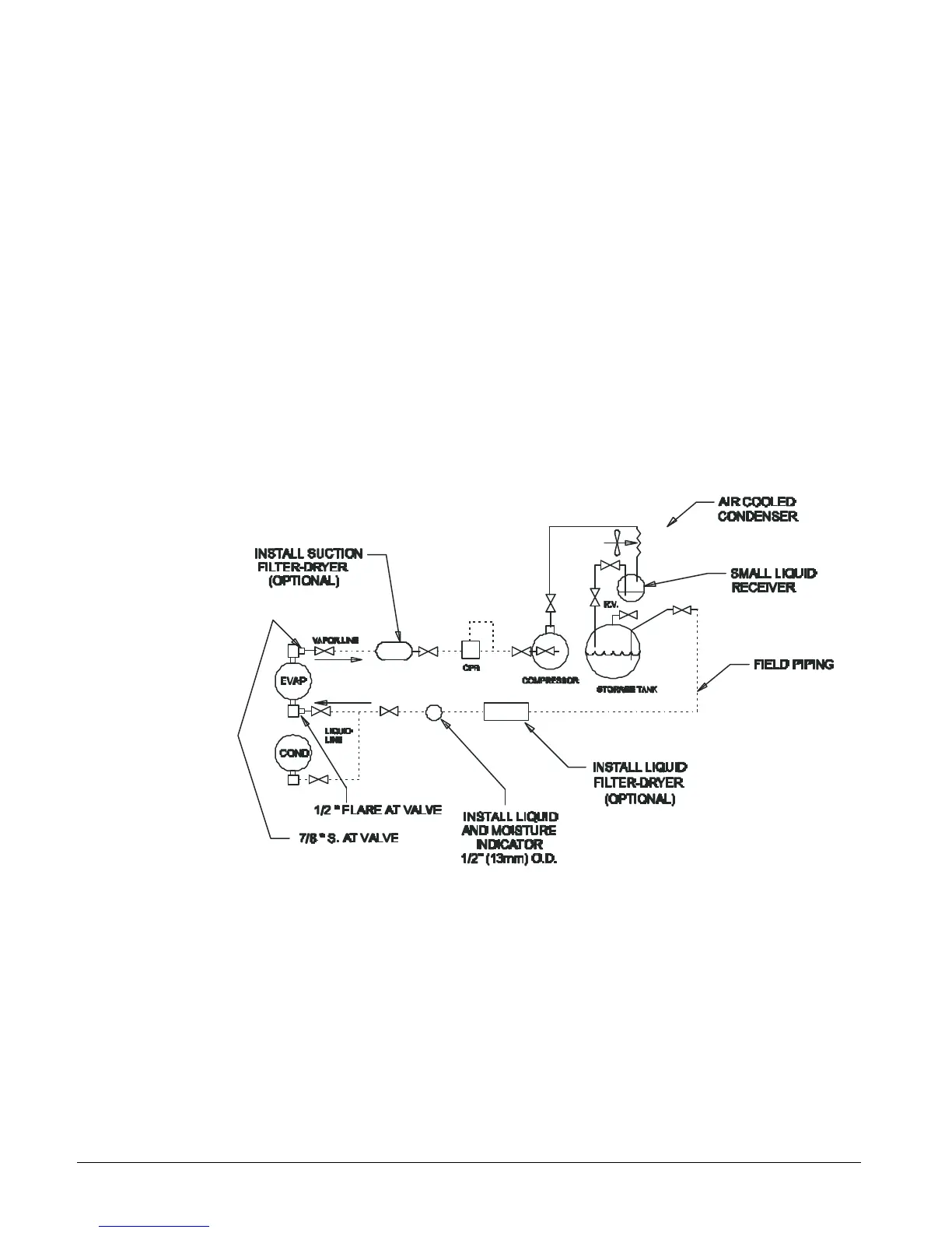
The schematic piping arrangement shown below is the normal method of installation. Transfer from the chiller is
accomplished by liquid refrigerant flow from the condenser into the storage tank. When liquid transfer is
completed, valving changes are made to draw out the chiller’s remaining refrigerant vapor through the suction
of the pumpout compressor, condense the vapor in the air-cooled condenser and transfer it to the storage tank.
Transfer from the storage tank to the chiller is initially by liquid/vapor flow until enough refrigerant is in the
chiller unit to start it. The chiller compressor will then draw refrigerant directly from the tank.