52 Product Manual PM WSC/WDC
Notes:
1. Compressor motor starters are either factory mounted and wired or shipped separate for field wiring. If
provided by others, starters must comply with McQuay specification 359A999. All line and load side power
conductors must be copper.
2. If starters are free standing then field wiring between the starter and the control panel is required. Minimum
wire size for 115 VAC is 12GA for maximum length of 50 feet. If greater than 50 feet, refer to McQuay for
recommended wire size minimum. Wire size for 24 VAC is 18 GA. All wiring to be installed as NEC class 1
wiring system. All 24 VAC wiring must run in separate conduit from 115 VAC wiring. Main power wiring
between starter and motor terminal is factory installed when units are supplied with mounted starters.
Wiring of free standing starter must be done in accordance with NEC, and connection to compressor motor
terminals must be made with copper wire and copper lugs only.
3. For optional sensor wiring see unit control diagram - Terminals AH1 through AH6. It is recommended that
DC wires be run separately from 115 VAC wiring.
4. A customer furnished 24 volt alarm relay coil may be connected between terminals 50 and 68 of the control
panel. The alarm is operator programmable. Maximum rating of the alarm relay coil is 25 VA.
5. Remote On/Off control unit can be accomplished by installing a set of dry contacts between terminals 9 and
64. If an additional point of On/Off control is required remove jumper from terminals 64 and 65 and install
the additional set of dry contacts.
6. Evaporator and condenser paddle type flow switches or pressure differential switches are required and
must be wired as shown. Field supplied pressure differential switches must be installed across the vessel
and not the pump.
7. A 115 VAC oil cooler solenoid (OC1) or a two solenoid 24 VAC oil cooler motorized valve. (OC1, OC2) are
two options required on some models. Refer to the installation manual and wire as shown.
8. Optional customer supplied 115 VAC 25VA maximum coil rated chilled water pump relay (CHWR 1 and 2)
may be wired as shown. This option will cycle the chilled water pump in response to building load.
9. The condenser water pump must cycle with the unit. A customer supplied 115VAC 25VA maximum coil rated
condenser water pump relay (CWR 1 and 2) is to be wired as shown.
10. Optional customer supplied 115 VAC 25 VA maximum coil rated cooling tower fan relays (C1 - C4) may be
wired as shown. This option will cycle the cooling tower fans in order to maintain unit head pressure.
11. Auxiliary 24 VAC rated contacts in both the chilled water and condenser water pump starters must be wired
as shown.
12. All wiring to be NEC Class 1.
Control Power
The 115 volt control power may be supplied from the starter or a 2 KVA transformer separate from the starter.
Either source should be properly fused with 20 amp dual element fuses or with a circuit breaker selected for
motor duty. If the control transformer or other power source for the control panel is remote from the unit,
conductors must be sized for a maximum voltage drop of 3%. Required circuit ampacity is 20 amps at 115 volts.
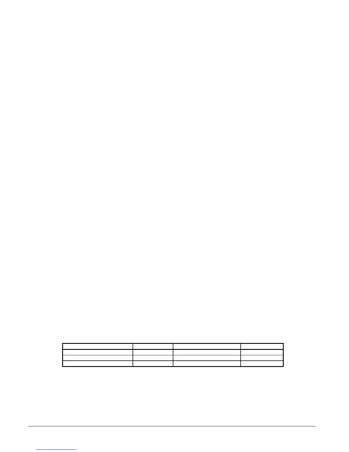
Conductor size for long runs between the control panel and power source, based upon National Electrical Code
limitations for 3% voltage drop, may be determined from the table below.
Control Power Line Sizing
Maximum Length, FT (M) Wire Size (AWG) Maximum Length, FT (M) Wire Size (AWG)
0 (0) to 50 (15.2) 12 120 (36.6) to 200 (61.0) 6
50 (15.2) to 75 (22.9) 10 200 (61.0) to 275 (83.8) 4
75 (22.9) to 120 (36.6) 8 275 (83.8) to 350 (106.7) 3
Notes:
1. Maximum length is the distance a conductor will traverse between the control power source and the unit control panel.
2. Panel terminal connectors will accommodate up to number 10 AWG wire. Larger conductors will require an intermediate junction box.