indication is invalid and should be ignored.
3. Press
DISPLAY to alternate between supply voltage
and frequency.
3-wire lead set connection
If an installation socket is not available and it is necessary to
connect to all three conductors, use the 3-wire lead set.
1. On a single phase system connect the red lead to phase,
the black to neutral and the green to earth.
2. Supply voltage and polarity are displayed.
3. Press
DISPLAY to alternate between supply voltage and
frequency.
Note: For connection to a three phase system, see
‘Determining Phase Sequence’.
When connected, the instrument will display the supply voltage
indicated in the following table:
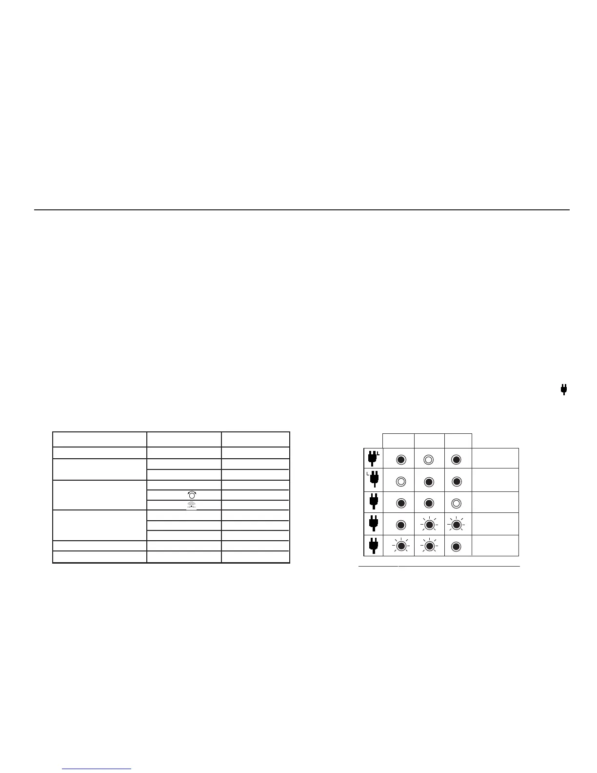
Polarity Indication
If connected to a single phase power supply by a plug or by the
3-wire lead set, three LCD ‘neons‘ marked
L-PE, N-PE and L-N
respectively will indicate supply polarity. If a voltage is detected
between their respective two wires, the ‘neon’(s) will activate. A
‘neon’ will usually flash if one connection is open circuit.
Note:- The presence of a voltage between phase and earth does
not prove earth continuity, as the earth could have a high
resistance and a voltage would still be measured. To test earth
continuity refer to the sections on loop resistance or RCD testing.
If
Setting A is set, the CM500 will automatically switch Line and
Neutral as appropriate, when in any of
LOOP, Re (earth) or RCD
test functions. This enables a test to be performed without
inverting the plug connections. The live terminal of the wall
socket is identified by the addition of a separate symbol
adjacent to the ’neons’. The Phase / Neutral reversal and symbol
display does not occur in Setting A Insulation and Continuity
ranges, and does not occur in Setting b.
Setting A - LOOP, Re (earth) and RCD
11
Mode
RCD Tests (all Currents)
Loop Resistance
Continuity
Insulation
Download to PC
Off
Switch Position
Voltage Display
L-PE
L-N
L-PE
L-PE
L-N
L-N
L-N
L-N
N-PE
No Display
Off
RCL
(MΩ
) L-N
(MΩ) N-PE
(MΩ
) L-PE
(Loop) L-PE/Re
(Ω) R
(Ω)
(Ω)
(Loop) L-L/L-N
(RCD) positions
Normal Supply
L-PE N-PE
L-N
L-N Reversed
Neutral Live
Neutral
Open Circuit
Earth
Open Circuit