1. Disconnect Phase, Neutral and Earth from the D.B.
2. Insert the power plug into an installation socket on the
isolated circuit to be tested.
3. Select (
MΩ) L-PE, L-N or N-PE as required.
4. Press either the
I or the TYPE key to display the test
voltage. Press again until the required test voltage is
displayed.
5. Press and hold the
TEST key.
6. Circuit resistance value is displayed.
7. Release the
TEST button, but maintain connection to allow
the test voltage to discharge.
Method of measurement
A current limited d.c. source is used, and the resistance is
calculated from measurements of the voltage and current. The
polarity of this d.c. source is as follows:-
Range +ve terminal -ve terminal
L-N Neutral (Black) Phase (Red)
N-E Neutral Earth
L-E Phase (Red) Earth (Black)
The voltage is only present when the test button is pressed. A
measurement of the terminal voltage is made before the test and
if this exceeds about 25 V the test is disabled. If d.c. voltage is
detected across any of the terminals a discharge resistor is
connected across it. The reading is stable with a circuit
capacitance less than 5 µF.
Loop Impedance measurement
Loop impedance measurement of 0,01Ω up to 3.00 kΩ can be
made via installation sockets using the plug terminated test lead,
or at any other convenient point on the installation using the two
wire lead set. If
Setting A is selected when using the plug
terminated lead set, the polarity of the mains socket is
immaterial. Line and Neutral will be swapped if necessary, and
an indication given on the display.
Setting b requires Line and
Neutral to be fixed.
The
CM500 will measure the loop resistance from the supply
end of the standard test leads, allowing for their resistance.
15
Test results may be adversely affected by supply voltage
fluctuations or electrical ‘noise’ during measurement. It is
recommended that tests are repeated and the results verified,
if measurement results are considered abnormal.
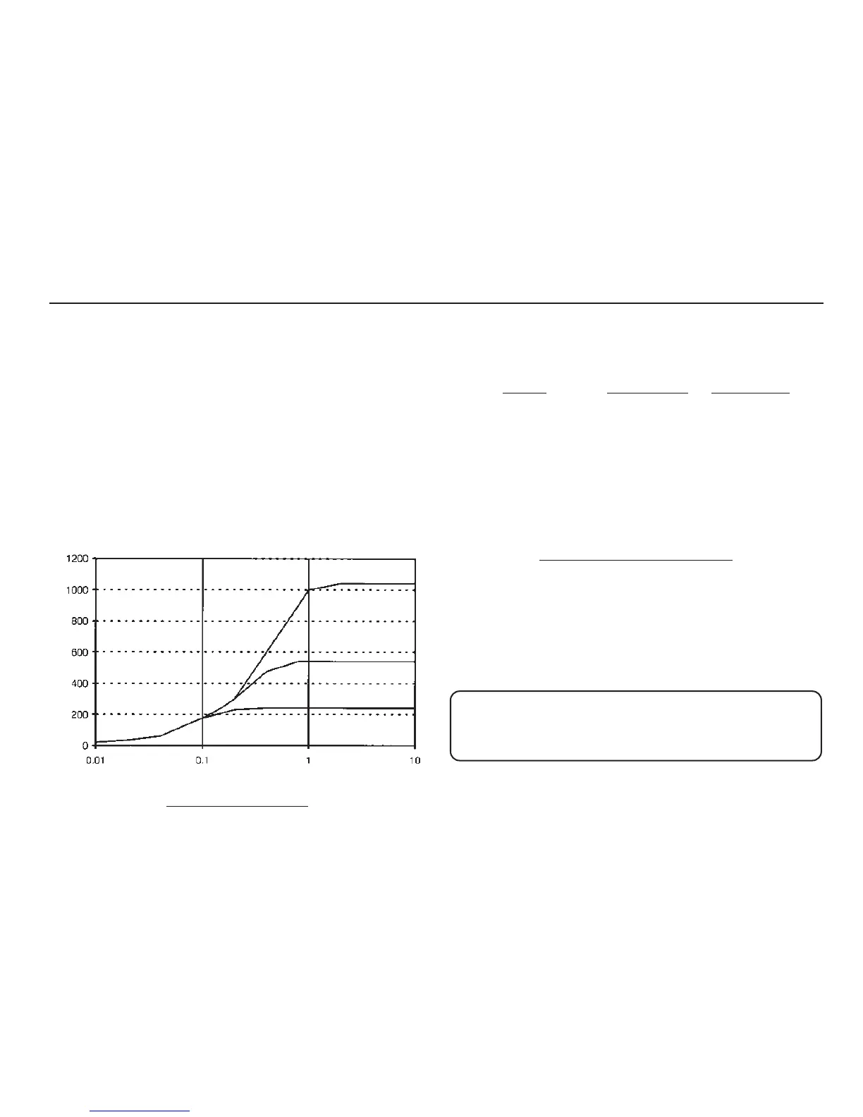
V
O
L
T
S
RESISTANCE - MΩ
1000 V
500 V
250 V
Insulation T
est Voltage