Safety Warnings 3
Initial Setup 4
General Description 6
Features, Controls and Connections 8
Operation 10
Backlight 10
Auto shut-off 10
Switched probe
SP2 10
Checking Earth Potential 10
Voltage and Frequency Measurement 10
Polarity Indication 11
Determining Phase Sequence 12
Continuity Testing and Low Resistance measurement 12
Test Lead Resistance Nulling 12
Low Resistance Continuity measurement 13
Continuity Bleeper 13
Low input resistance voltmeter 13
5Ω Threshold 13
Insulation Testing and High Resistance measurement 14
Loop Impedance Measurement 15
Bonded Metalwork Testing 16
Prospective Short Circuit Current (PSCC) 17
PFC measurement accuracy 17
Earth Loop Resistance measurement at 15 mA 17
RCD Testing 18
No Trip Tests 20
Trip Tests 20
Auto Sequence RCD Test 22
Earth Resistance Measurement 24
Earth Electrode Resistance Measurement 24
Condition and Warning Indication 26
Test Results, Storage, Deletion and Retrieval 27
Serial Cable Connections 30
Specification 31
Accessories 35
Publications 36
Basic and Service Error calculation 37
Repair and Warranty 39
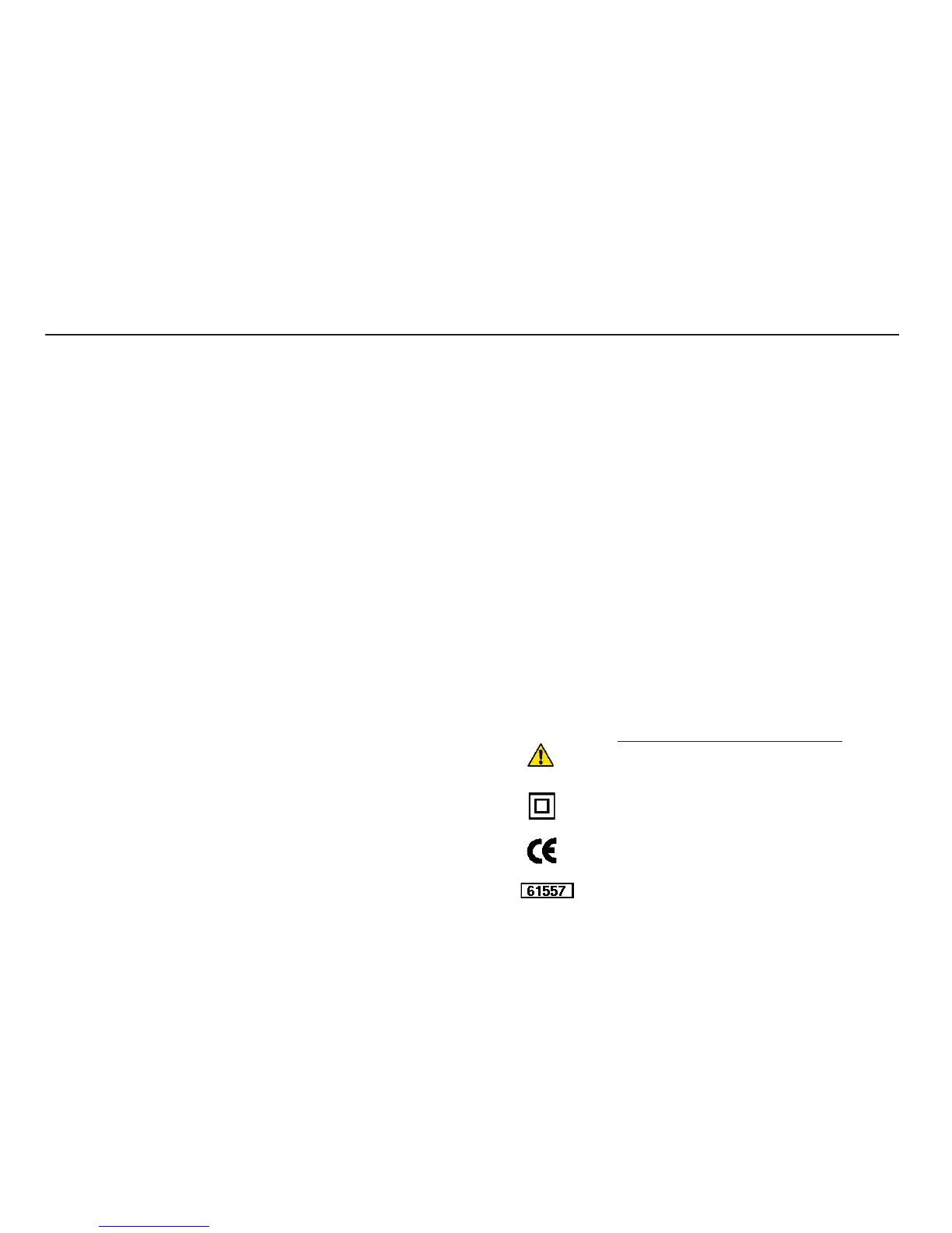
Symbols used on the instrument
Caution: Refer to accompanying notes
Equipment protected throughout by
Double or reinforced Insulation (Class
II)
Equipment complies with current EU
Directives
Complies with IEC / EN 61557
2
Contents