3. Switch Off and isolate the installation under test.
4. Disconnect the earth electrode.
5. Using the 2-wire lead set, connect the black lead to the
earth electrode under test.
6. Select
Re.
7. Carefully connect the red lead to the phase conductor
of the incoming mains supply on the distribution board.
8. Supply voltage and polarity are displayed.
9. Press the
TEST button.
10. Measured earth resistance value is displayed.
Note:- Though displayed, polarity indications are invalid using
the 2-wire test lead set, and should be ignored.
11. Disconnect the red and black leads. Switch off the
CM500.
12. Firmly re-connect the earth electrode.
13. Carry out a continuity test between the
PE conductor and
the earth electrode and confirm that a valid connection has
been made.
14. Switch on the supply.
15. Carry out a loop resistance test.
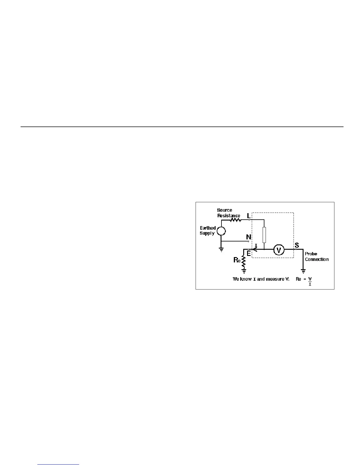
Method of measurement
The earth resistance is measured by taking a current from the
supply and injecting it into the resistance to be measured. The
voltage change across the earth resistance is measured by the
use of a remote probe 20-30 m away from any earth electrodes.
The test current will vary from 15 mA to 25 A, depending on
supply voltage and the loop resistance value. The test duration
will depend on the loop resistance value.
Possible sources of error
As with the loop resistance measurements, the reading depends
on a measurement of the supply voltage and therefore noise or
transients caused by other equipment during the test could
cause an error in the reading. One way to check for these is to
do two tests and look for any difference in value. The instrument
will detect some sources of noise and warn the user where some
instruments may have given an incorrect reading.
The measurement depends on the position of the probe. The
probe must be positioned away from any part of the installation
under test, so that it provides a valid reference earth. For a single
earth electrode, the distance of 20 m is found to be sufficient. Be
careful of secondary earth paths, such as service pipes. The best
way to confirm the measurement is to try two probe positions.
25