2-10
2.2 Device Structure
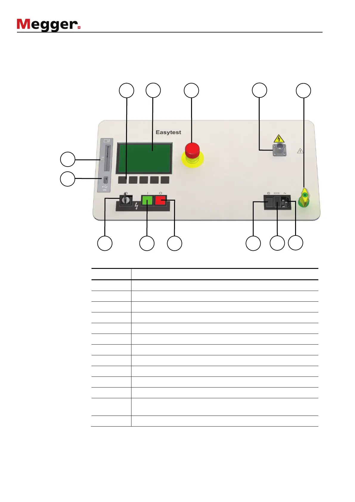
Front view The following illustration shows the front view of the Easytest:
Controls and
connections
The Easytest system has the following controls and connections:
Control Description
1 Membrane keypad
2 Display
3 Emergency off switch
4 HV output
5 HV “interlock” key-operated switch
6 HV on button
7 HV off button
8 Power switch
9 Fuse
10 Power supply
11 Protection earth socket
12 Smartcard slot used to log test data on WinkisVLF system card
(optional)
13 USB slot used to log test data on a USB stick (optional)
 Loading...