3-14
3.2 Switching On the System
Switch-on procedure
Before it is switched on using the power switch (8), the device is in the ‘off’ state.
this state, the HV output is earthed. For devices with external vol
(optional),
the HV source and the internal earthing of the device are separated from
the HV output by the HV circuit breaker.
The capacitive voltage divider for measuring
the external voltage (optional) is directly connected to the HV output.
When the power switch is turned on, the system is in the ‘standby’
are activated and the display shows the welcome screen, followed by the main menu.
3.3 Safety Mechanisms
Introduction From ‘standby’ mode onwards, the system is constan
tly monitored by a number of
safety mechanisms.
If one of these mechanisms reports a malfunction, either the entire system is
stopped
(coming along with an individual error message) or, in the case of a test voltage
deviation, the system solely indicates the problem.
If a running test is interrupted
, the cable under test is discharged via the internal
discharge switch. If the interruption is caused by the optional e
protection (see next page), the cable under test is not discharged!
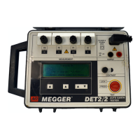
Interlock
(key-operated switch)
You can activate or deactivate an HV interlock using the key-
operated switch (5). In the
vertical position
, the HV interlock is activated and no measurements can be
performed. The display shows the following message:
You can deactivate the HV interlock by turning the key a quarter turn clockwise.
Afterwards, the system message has to be acknowledged using the clear soft key.
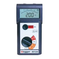
‘F-Ohm’ safety circuit
The F-Ohm safety circuit monitors the loop resist
ance of the system earth (test cable
screen) and the safety earth.
If the resistance is more than 6 ohms, a system
message notifies you of the fault in the safety circuit.
The operator must rectify the cause of the fault and then press the clear soft k
continue using the system.
F-Ohm
clear
Key-operated switch
clear