3-13
Connection
diagram
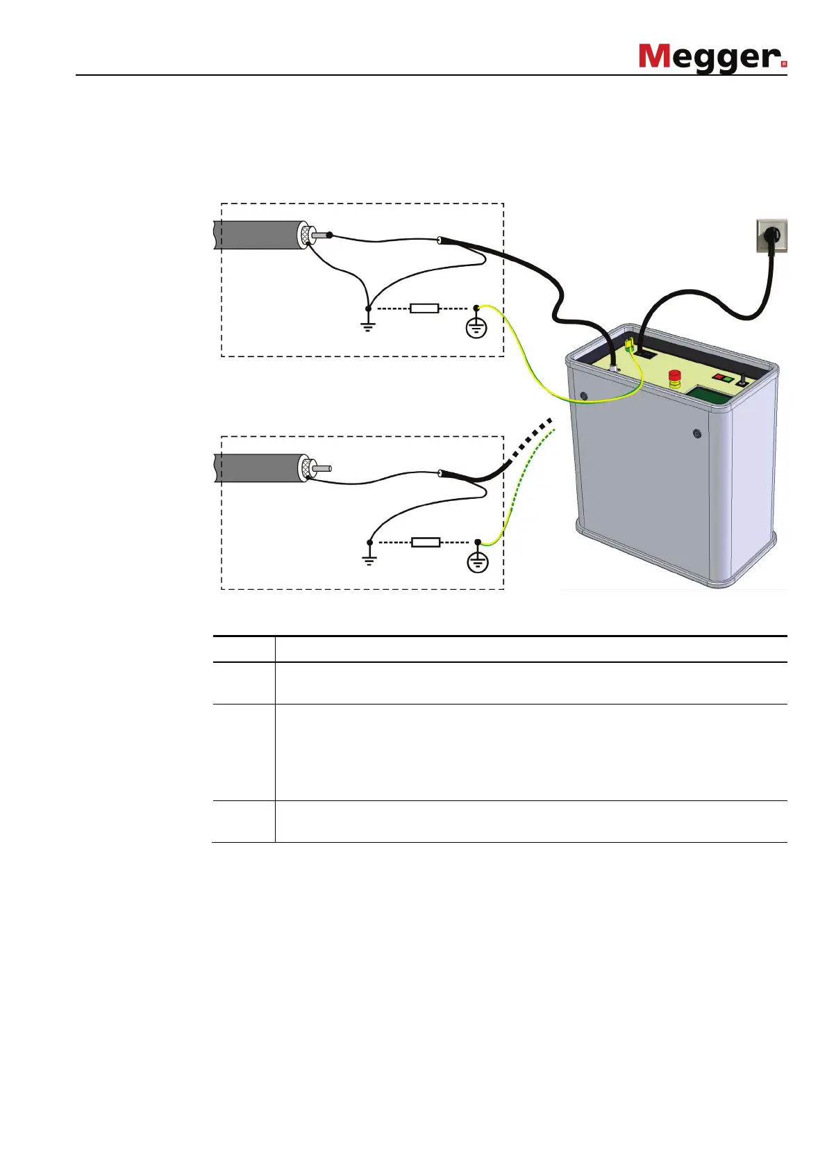
The following illustration shows the basic connection diagrams for the various
modes:
Connection
sequence
Connect the system in the following order:
Step Action
1 Connect the earthing cable to the protective earth of the station and then fasten
it to the earth socket (11) of the test system.
2 Plug the high voltage connection cable into the HV output of the test system (4)
and fasten it by turning the lock.
Then connect the HV connection cable to the phase or the screen of the cable
under test (depending on the operation mode). The screen of the HV connection
cable has to be connected to system earth.
3
Plug the supplied power cable to the power connection of the test system (10)
and connect it to a mains socket.
Protective
earth cable
HV connection
cable
Power cable
Sheath test / pinpointing
DC and AC test