14
RESIDUAL CURRENT DEVICE [RCD] TESTING
The MFT can perform the following RCD tests:
1/2I Non-tripping test at half the rated RCD trip current for 2
seconds, during which the RCD should not trip.
I Tripping test at the rated RCD trip current. The trip time will
be displayed.
5I Tripping test at 5 x the rated RCD trip current. The trip time
will be displayed in milliseconds.
DC 1/2I, I and 5I tests can be performed as DC tests.
0 or 180°
Some RCDs are sensitive to the polarity of the supply, i.e
whether the test current is applied with the instantaneous
voltage rising or falling. Trip tests should therefore be
performed with both polarities 0° and 180° and the
maximum time recorded.
Ramp Test
Used to check the trip current of an RCD.
Note: The Breaker symbol indicates whether the test
function selected is a NON-TRIPPING or TRIPPING test:
CLOSED = NON-TRIPPING test
OPEN = TRIPPING test
1/2 I RCD Testing
Set the LEFT [RCD] rotary range knob to the [ 1/2I ] RCD test range.
Set the RIGHT [mA] rotary range knob to current rating of the RCD under
test.
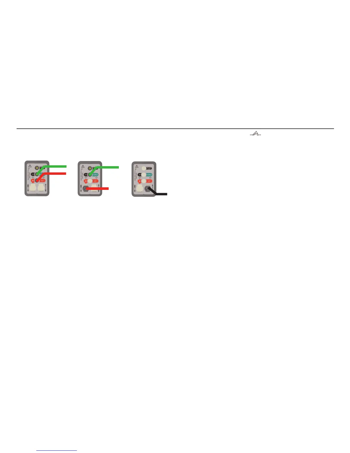
Test lead set: OPTION 1, 2 or 3
1. Ensure the right hand Rotary knob is set to the correct range
for the RCD under test.
2. Press the YELLOW TEST button.
3. After 2 seconds the message >1999 ms is displayed.
4. If enabled, the touch voltage is displayed on the bar-graph
display.
If the RCD trips unexpectedly the message ‘trP’ will be
displayed.
1 x I RCD Testing
Set the LEFT [RCD] rotary range knob to the [ I ] RCD test range.
1. Press the YELLOW TEST button.
2. The RCD trip time is displayed.
3. If enabled, the touch voltage is displayed on the bar-graph
display.
OPTION 3
Mains plug
test lead
OPTION 2
Switched
probe
OPTION 1
2 wire lead
set
GREEN
GREEN
RED
PLUG
PROBE
 Loading...