Set the left hand rotary range knob to the required INSULATION Range.
250 V Insulation measurement to 99.9 MΩ
500 V Insulation measurement to 299 MΩ
1000 V Insulation measurement to 499 MΩ
(The position of the right hand rotary range knob does not matter.)
To initiate insulation testing press and hold the YELLOW TEST button on
the instrument or the switched probe if connected.
Release the test button after the displayed reading has settled.
TEST LOCK
To lock down the test button press the YELLOW TEST button followed by
the RED LOCK
L button.
A warning triangle
G will appear in the display while the test lock is active.
Press the YELLOW TEST button to stop the test.
Note:- A 1000 V warning is displayed whenever the 1000 V range is selected
and the test button pressed
Warning: The test voltage will be permanently present on the test probes
or crocodile clips when in the locked modes.
Notes:- Auto discharge - Auto discharge facility automatically and safely
discharges connected circuit after test via 250 kΩ resistor.
Live circuit warning - operates when connected to Live circuits > 25 V.
Test Inhibited - an audible alarm operates at >55 V. The instrument
will not perform a test until the voltage source has been removed.
Method of measurement
A current limited (2 mA) d.c source is used, and the resistance is calculated
from measurements of the voltage and current.
The voltage is only present when the test button is pressed or the test lock
is active. A measurement of the terminal voltage is made before the test and
if this exceeds 55 V the test is disabled. The reading is stable with a circuit
capacitance up to 5 µF.
LOOP IMPEDANCE [LOOP] TESTING
Loop impedance measurement can be made via installation sockets using
the plug terminated test lead at any other convenient point on the
installation, using a two/three wire lead set.
The MFT will measure the loop resistance from the supply end of the
standard test leads, allowing for their resistance.
NON TRIPPING LOOP TESTS [NO TRIP]
Set the LEFT rotary range knob to the required LOOP range as
described below:
(The position of the right hand rotary range knob does not matter.)
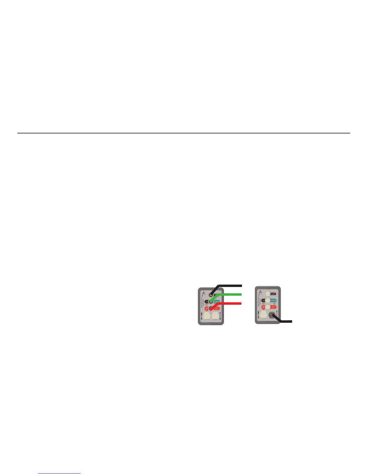
OPTION 1
3 wire
measurement
OPTION 2
Mains plug
test lead
BLACK
GREEN
RED
PLUG
9
 Loading...