High Current loop test 10
P-N and P-P loop test 11
PFC 12
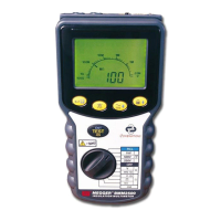
Residual current device (RCD testing) 14
1/2I, I, 5I, 0 & 180° 14
RCD auto test sequence (MFT1552 only) 15
Ramp testing 15
DC Sensitive RCDs 16
Bluetooth downloading (MFT1553 only) 17
Technical specification 21
Accessories 24
Repair and warranty 25
Appendix - Additional Bluetooth information
(Attaching a Dongle) 26
Symbols used on the instrument are:
F Caution: risk of electric shock
G Caution: refer to accompanying notes
t Equipment protected throughout by Double
Insulation (Class II)
c Equipment complies with current EU directives.
Maximum nominal system voltage of 500 V
Maximum 300 V a.c. CAT III to Earth
CONTENTS
3
Safety Warnings 2
Description 4
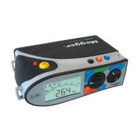
Overview of MFT1500 Series 4
Instrument layout 4
Display 4
Control panel 4
Front switch panel 4
Connection panel 4
Test leads 4
Battery /fuse warning, fitting and replacement 5
Setup 5
Operation 6
General operation 6
Live circuit warning 6
Test button lock 6
Backlight (MFT1502/1552 and 1553 only) 6
Auto shut-off 6
Polarity indication 6
Illuminated switched probe 6
Operation 6
Voltage measurement (V) 7
Continuity 7
Continuity measurement 7
Lead null 8
Continuity buzzer 8
Buzzer threshold 8
Insulation 8
Insulation resistance 8
Insulation voltage ranges 8
Test lock 9
Loop impedance 9
NO TRIP (15 mA) loop test 10
G
>500V
Max 300 V
CAT III
g
 Loading...