6
OPERATION
GENERAL OPERATION
Note: These functions are generally applied and not limited to an
individual test function.
Live circuit warning - Test inhibit
Testing is automatically inhibited if:
During insulation testing - an external voltage >55 V is
present on the terminals
During continuity testing - a voltage >10 V is present on the
terminals
During RCD or No-Trip loop testing - a voltage >270 V is
present
During Loop testing - a voltage >480 V is present
Test button lock
To lock the test button hold down the RED
L test lock button whilst
holding down the YELLOW TEST button.
Intelligent backlight (MFT1502/1552/1553 only)
Both the display and range knobs have a backlight. To activate, press the
BLACK
J
button.
To disable the Intelligent backlight function, press the BLACK
J
button
and the RED
L
lock button together.
Repeat to enable the intelligent backlight.
Instrument auto shut-off
Automatically activated after 5 minutes of instrument inactivity.
To restore operation press the RED lock button or switch the instrument
off and on.
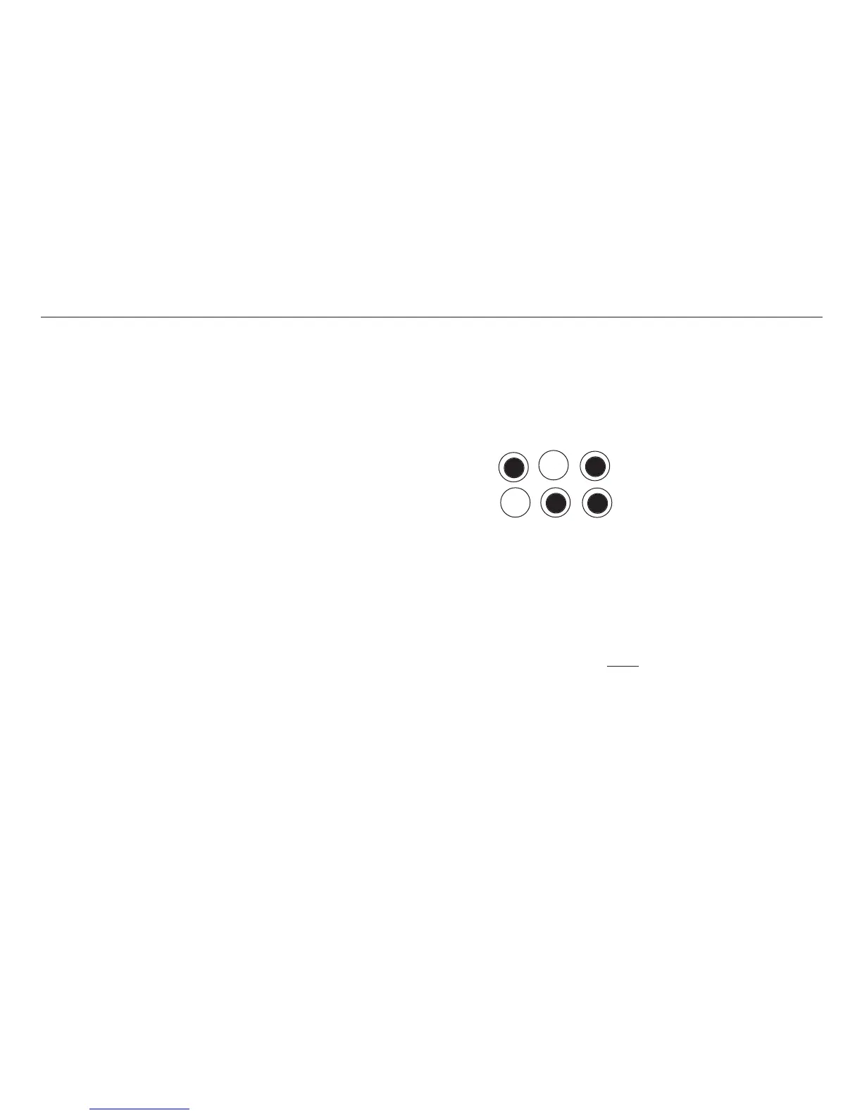
Polarity indication
If connected to a single-phase power supply by a plug or by the 3-wire lead
set, three LCD ‘neons‘ marked L-PE, N-PE and L-N respectively will indicate
supply polarity.
If a voltage is detected between their respective two wires, the ‘neon’(s)
will activate.
L-PE N-PE L-N
Correct supply indication
Live –neutral swapped
Any other combinations should be investigated further. However the LCD
'NEONS' cannot be relied upon to identify circuit correctness and are for
guidance only.
Note:- The presence of a voltage between phase and earth does not prove
earth continuity, as the earth could have a high resistance and a voltage
would still be measured. To test earth continuity refer to the sections on
loop resistance or RCD testing.
Warning: The LCD 'Neons' are invalid
when using the two wire lead-set
and should be ignored.
ILLUMINATED SWITCHED PROBE SPL1000 (
MFT1502/1552/1553 ONLY)
The Illuminated switched probe accessory replaces the RED 4 mm test
lead. It can be used anywhere that the 4 mm lead set is specified in this
user guide, and it will also add extra resistance to a loop test measurement.
Operation (SPL1000)
The YELLOW button duplicates the function of the TEST key on the
instrument, allowing quick and easy testing.
 Loading...