22
Operation
Useful information
Always press the GFCI
TEST
button on the GFCI to ensure the function works.
It is recommended the GFCI test button is tested after the timing tests above are complete. This can identify
GFCIs that may stick or fail if not checked periodically.
Ground resistance measurement
The Megger MFT70 offers a unique solution to the measurement of ground or ground electrode (rod) supporting
2 and 3 wire measurements:
This model can use an optional current clamp (Megger Current Clamp) to measure electrode (rod) resistance
without disconnection, leaving the installation grounding system intact (Attached Rod Technique, ART).
Additionally, they can drive an optional voltage-inducing clamp (Megger Voltage Clamp) which, in conjunction
with the Megger Current Clamp, can be used to make stake-less measurements of the Grounding system.
Refer to “Ground resistance testing – Basic principles” on page 34
Connection terminals
The terminal references used on the MFT are:
X
C
P
The terminal colours correspond to the ground test lead set, not the standard test leads shipped with the MFT70.
Touch voltage limit
Adjust touch voltage limit to 25 V or 50 V depending on location. Refer to “Touch voltage display” on page 21.
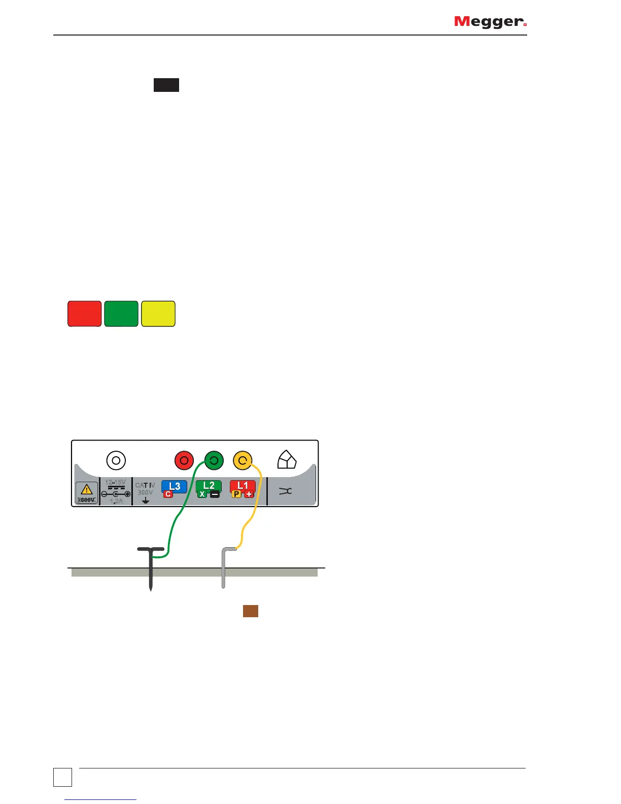
Making a measurement - two pole resistance measurement
1. Connect the instrument as shown below.
I
CAT IV
300V
12-15V
1.2A
Electrode
under test
Potential
stake
2. Set the left hand rotary selctor switch to
RE
.