9
Introduction
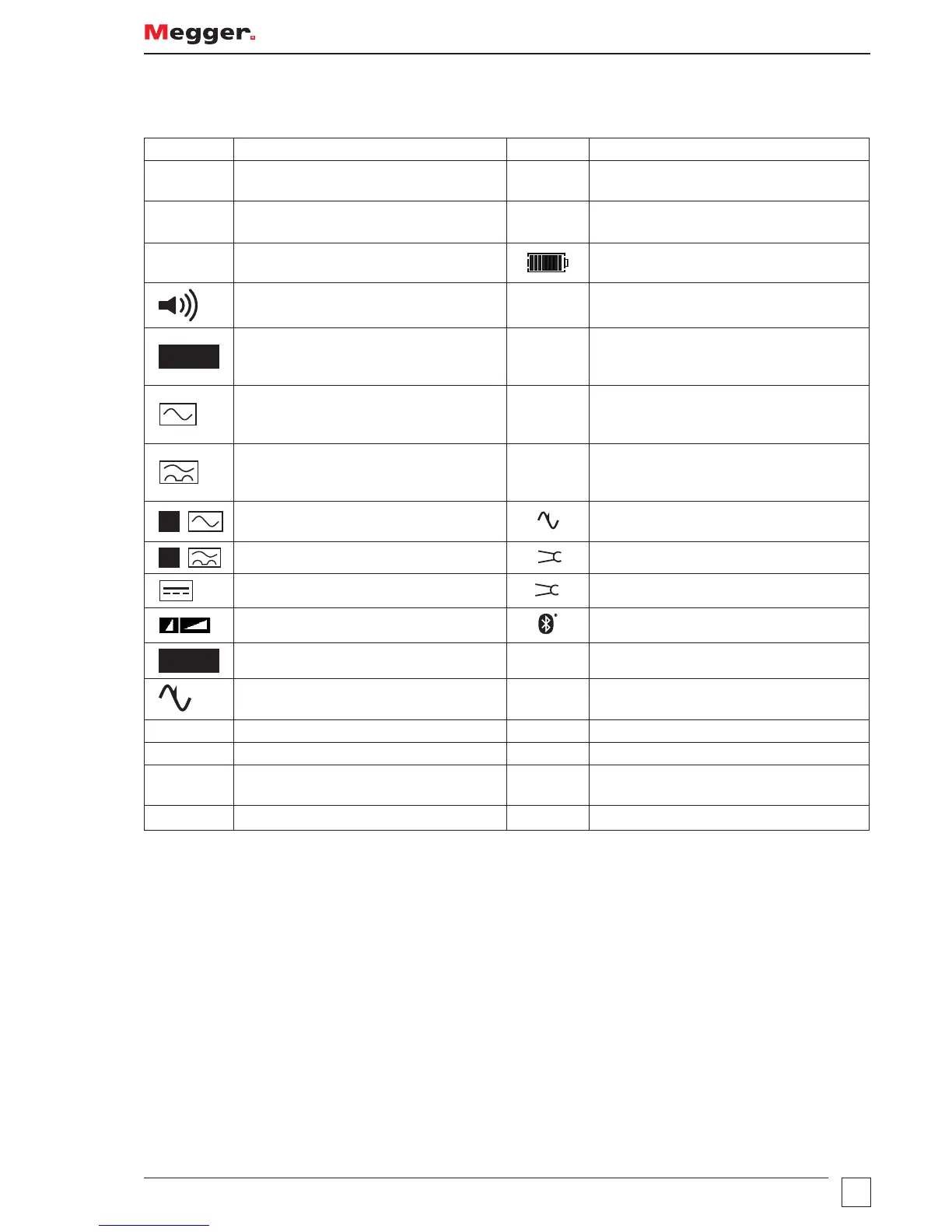
Display symbols
Symbol Meaning Symbol Meaning
l
Test function locked on (also used to
indicate a change is saved in setup)
G
Warning triangle – instruction to refer to
this user guide
z
Test lead null active
f
Fuse blown
U
L
= 50V
Touch voltage limit (and Ground test
voltage) set to 50 V (change setup)
Battery indicator
Buzzer enabled NiMH
Battery type set to rechargeable NiMH -
Change in “Battery” on page 27
AUTO
GFCI test in AUTO mode >100 V
Indicates that the ground noise voltage
exceeds the instrument measurement
capability (test is inhibited)
Type AC GFCI selected Rp (Rs)
Potential stake (P stake)
resistance exceeds range for accurate
measurement
Type A GFCI selected Rc (RH)
Current stake (C Stake)
resistance exceeds range for accurate
measurement
S
Type S GFCI (Type AC)
V
Ground noise voltage exceeds range for
accurate measurement of resistance
S
Type S GFCI (Type A)
V
Megger Voltage Clamp error
Type B GFCI selected
I
Megger Current Clamp error
Fast or Full RAMP test selected Bluetooth
®
enabled
TEST
Instrument is running a test
T
Instrument is too hot, allow to cool
Ground loop noise detected.
N<->L Live and neutral connections reversed
Zref Reference loop measurement
R1+R2
Loop measurement with Zref value
automatically deducted
ZMAX
Loop maximum measurement
NOTE: Some features detailed within this user guide are model dependent. Not all features appear on all models.