24
Status information
during the test
procedure
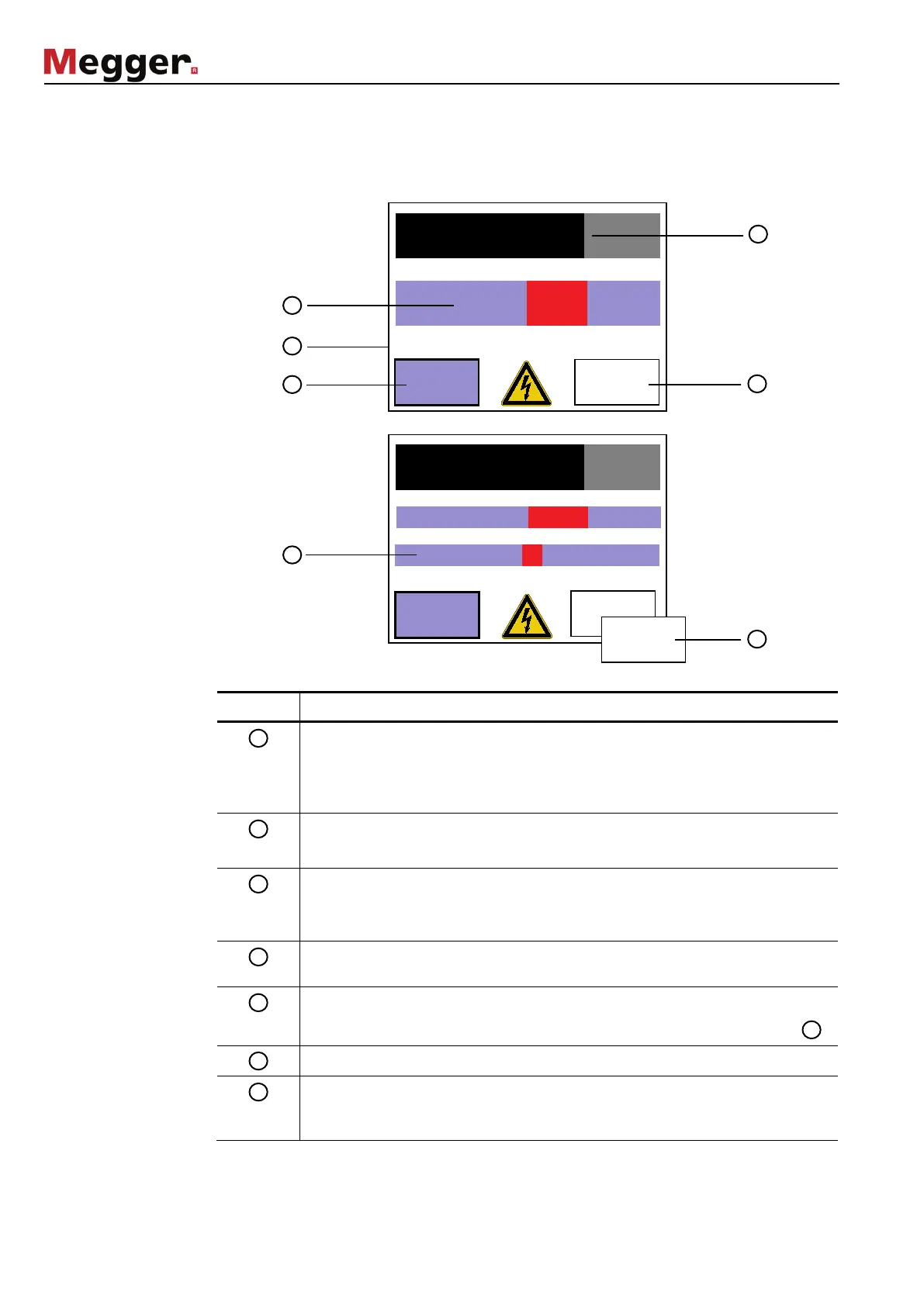
While the test is running, the user is kept continually updated regarding current
parameters and results. The screen content does differ in dependence of the respective
operation mode as shown in the figures below:
Segment Description
Remaining test duration in minutes. The black bar represents the remaining
amount of time.
In continuous operation, the cumulative test duration is displayed instead of
the remaining test duration.
Actual present test voltage value as RMS or peak value.
The red bar represents the instantaneous value.
Specified test settings (test voltage, total test duration, frequency).
If a frequency adaption took place during the start of the test, the frequency
value is written in green.
Stop button to interrupt the test. A test interrupted using the Stop button
cannot be resumed!
Details button to access the detail view (see next page).
In sheath test and sheath pinpointing mode, this button is replaced with .
Leakage current indication (DC modes only).
This button is available in sheath test and sheath pinpointing mode only and
can be used to adjust the test voltage level within the specified range (see
section 4.3.2).
-6 -3 0 3 6
U_set=3.8kV(RMS) t_set=60:00min f=0.10Hz
Stop
Details
3.8kV(RMS)
-6 -3 0 3 6
-1000 1000
U_set=5kV t_set=60:00min
Stop
Details
00:42:29
C modes