25
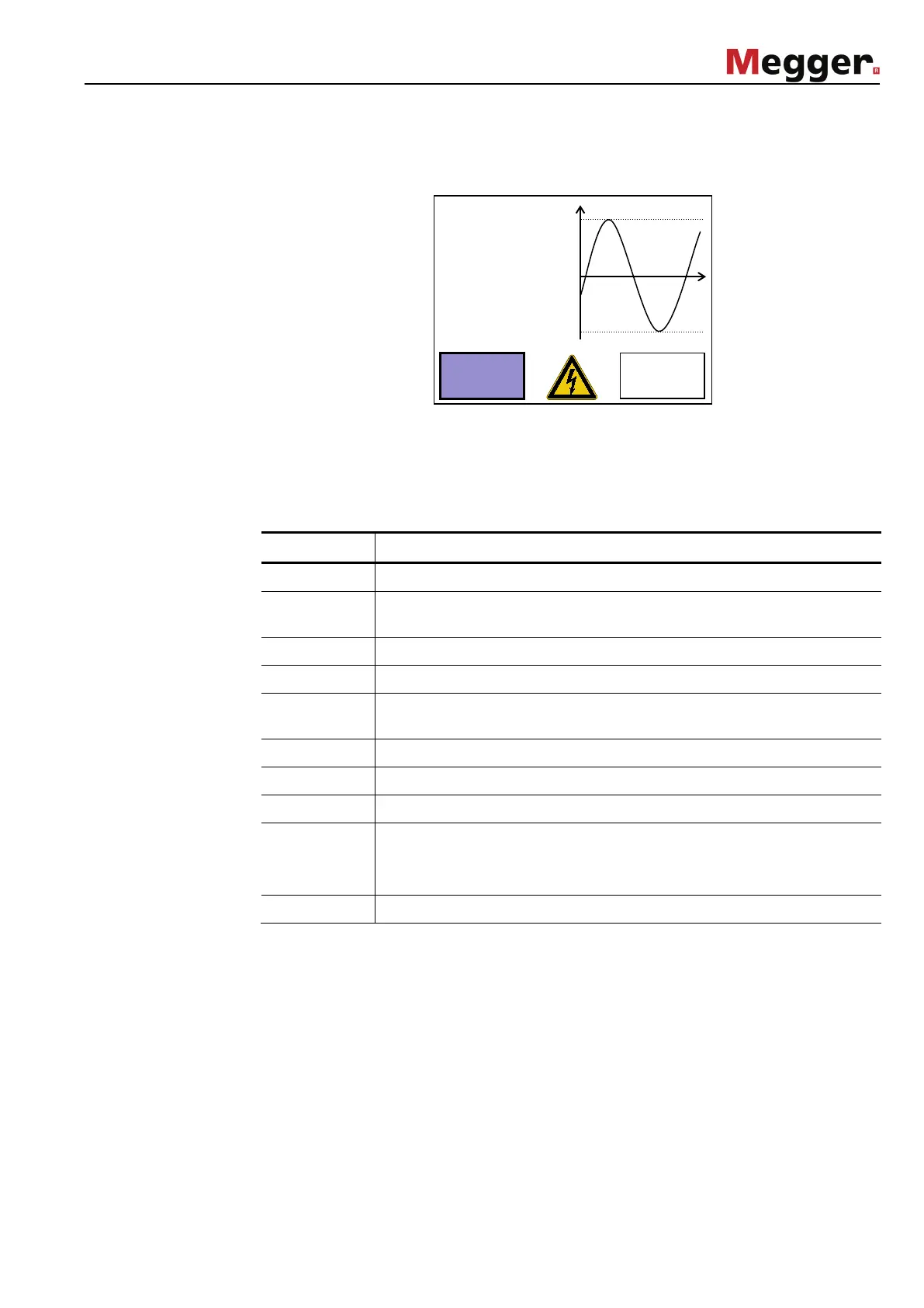
Detail view
The Details button can be used to display details on the measurement in progress at any
time:
On the right side of the detail view, the test voltage characteristics (AC voltage test) or the
characteristics of the leakage current (DC voltage test) are drawn in real time in a
diagram. By using the Scroll button and turning the rotary encoder, the user can at any
time scroll back to earlier time points.
On the left side of the display, the following test parameters are shown according to
operating mode:
Math symbol Description
V(Peak) Peak value of the AC test voltage
V(RMS) Effective value of the sine wave test voltage (updated after every
period)
V Present value of the DC or rectangular wave test voltage
I(PEAK) Peak value of the AC test current
I(RMS) Effective value of the sine wave test current (updated after every
period)
I Present value of the DC or rectangular wave test current
RLoad Load resistance (result of load recognition)
CLoad Load capacity (result of load recognition)
f Test frequency
If a frequency adaption took place during the start of the test, the
frequency value is written in green.
t_set Total test duration
Back
Scroll
-
V
V
R
C
-5.0kV
-4.2mA
μF