SERVICE - UIS
J
13
J
4
J
2
page 12
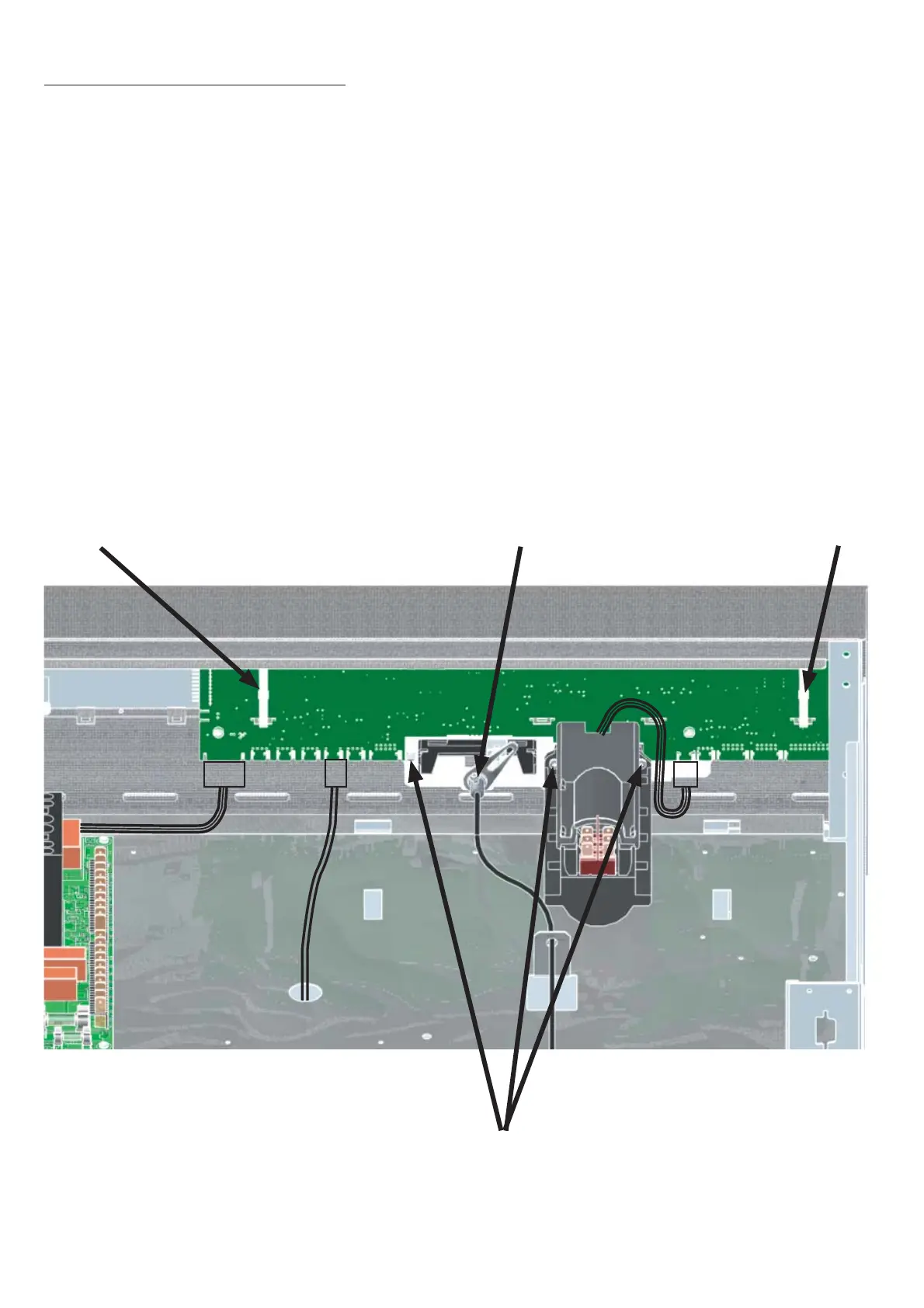
11. Replacing controller (BASIC)
Pull out the mains supply plug!
Remove the housing cover
Pull off the turn control knob towards the front
Cut the cable binder with the side cutters and remove it
Release the screw from the air flap spindle and remove the spindle
Disconnect the cable (8-way) for power supply from controller location J13
Remove connector (4-pin) for Pt100 working controller from controller location J4
Remove connector (4-pin) for main switch from controller location J2
Release three fixing screws (see ill.)
Remove the controller towards the back
•
•
•
•
•
•
•
•
•
•
Cable binder
Fixing screws
controller/display
Screw air flap spindle
Cable binder
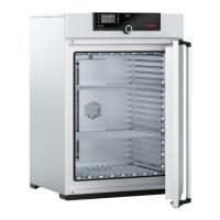
Example INB 200