85-03-01194 FV48 Page 47
3.4 PLUMBING TECHNICAL REFERENCES
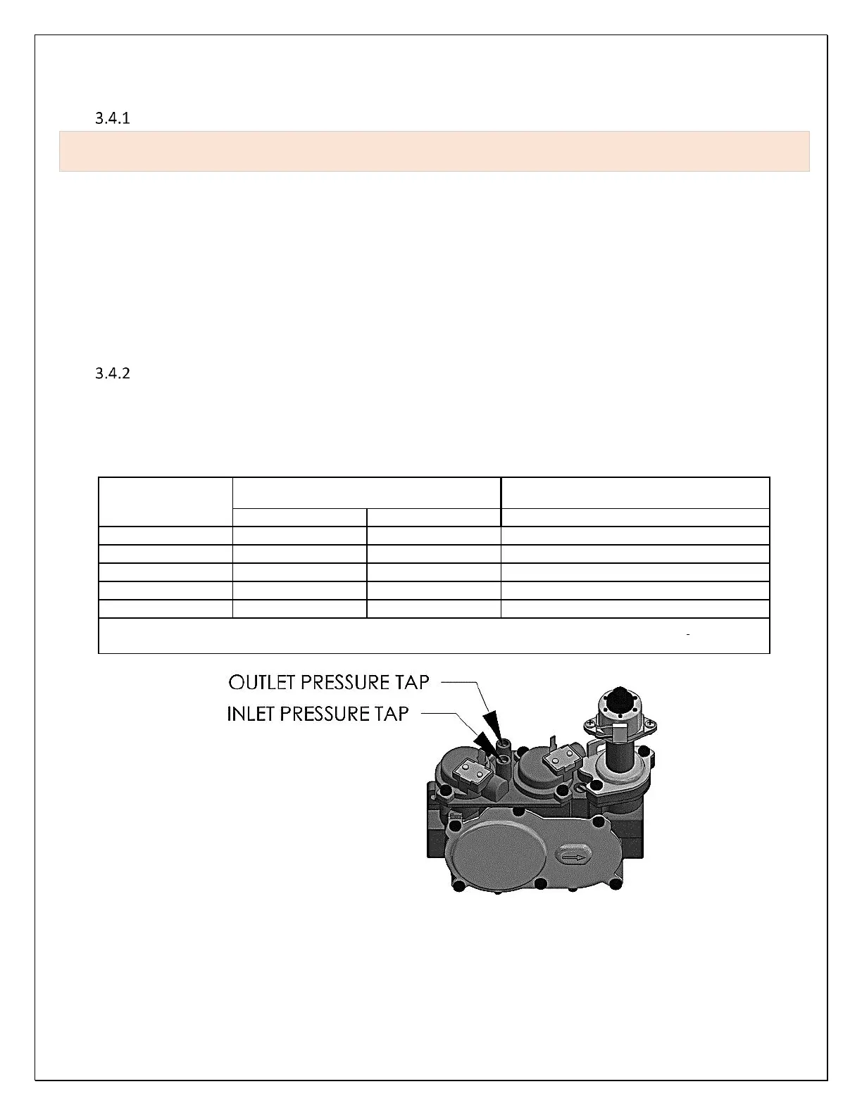
Gas Supply Requirements
NOTE: if Fireplace is to be operated with LP gas, see Chapter 4.10 Natural Gas to LPG Conversion in this
manual before proceeding.
CORRECT GAS PRESSURE AND PROPER GAS SUPPLY LINE SIZING IS IMPERATIVE TO THE SUCCESSFUL PERFORMANCE OF YOUR
MENDOTA GAS FIREPLACE. BE SURE THE GAS SUPPLIER OR PLUMBER CAREFULLY CHECKS FOR CORRECT GAS PRESSURE AND
GAS LINE SIZING WHEN INSTALLING THE FIREPLACE.
IT IS CRITICAL TO CAREFULLY CHECK FOR GAS LEAKS WHEN HOOKING UP THE FIREPLACE. CHECK WITH SOAP AND WATER
SOLUTION OR COMBUSTIBLE GAS SNIFFER.
BE SURE TO INSTALL CSST FLEX GAS LINE WITH BRASS-TO-BRASS FITTINGS TO PREVENT GAS LEAKS AT CONNECTIONS.
GAS SUPPLY PIPING MUST INCLUDE A DRIP LEG TO ELIMINATE THE POSSIBILITY OF CONTAMINANTS ENTERING THE GAS
TRAIN. ADHERE STRICTLY TO LOCAL AND NATIONAL CODES.
Gas Supply Line Sizing
This Mendota Gas Fireplace comes equipped with a 1/2" N.P.T. Female inlet. Gas supply piping must enter the Fireplace cabinet
on the left side.
Use the table, below, to determine the proper gas line diameter that must be installed to run from the supply regulator to the
factory installed manual shutoff valve. Refer to the following table for proper gas pipe diameters.