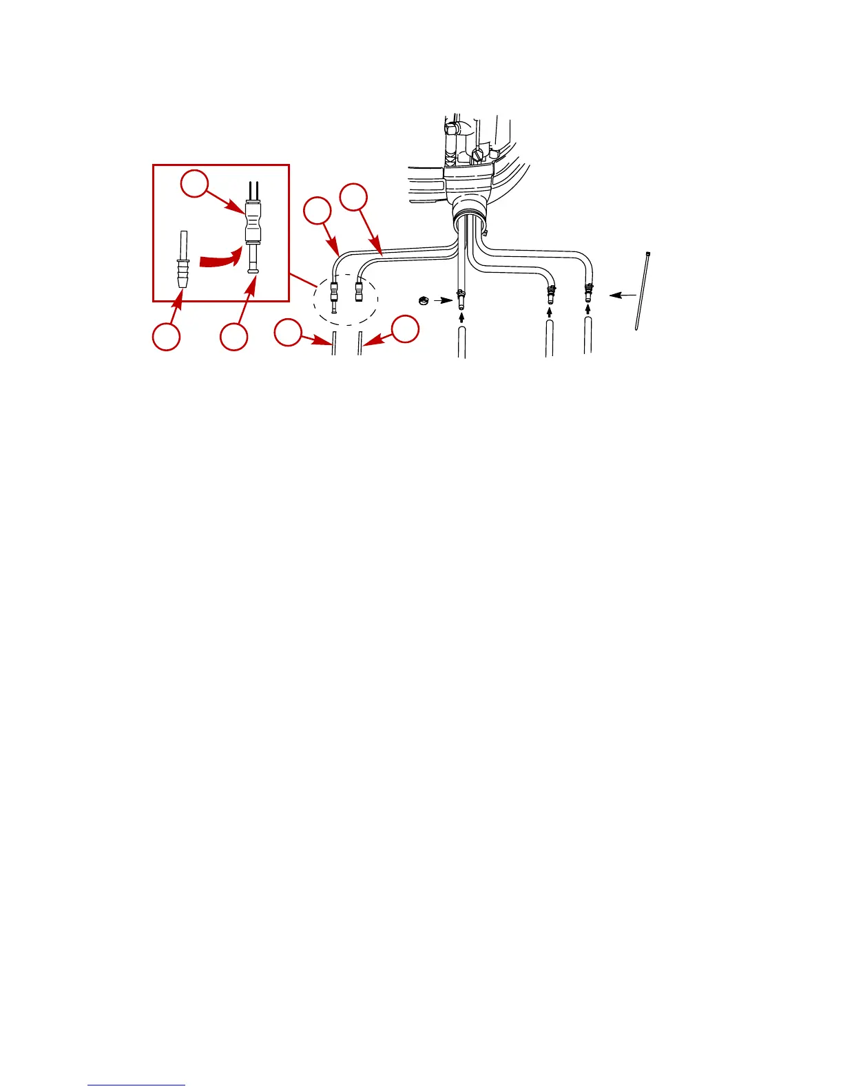
a - Speedometer water pick-up tube
b - Water pressure tube
c - Coupler
d - Plug
e - Barb hose fitting
f - Speedomer hose
g - Water pressure tube
Shift and Throttle Cable
COUNTER ROTATION OUTBOARDS
Counter rotating (left hand) gearcases can be identified by a "L" stamped into the end of the propeller
shaft.
The Quicksilver Dual Engine Console Mount Control is required to shift the counter rotation outboard.
The installation instructions shipped with the control explain the procedure required to connect this
control to a counter rotation outboard.
IMPORTANT: If the counter rotation outboard is rigged similar to a standard rotation outboard OR if a
standard rotation outboard is rigged similar to a counter rotation outboard, the reverse gear and bearing
in the gearcase must function as forward gear. The reverse gear/bearing is not designed to carry the
sustained loads that are generated when running under constant high RPM and thrust conditions.