f. Release the reusable cable tie.
a - Fuel pump
b - Fuel pump inlet hose (from fuel filter)
c - Fuel pump outlet hose (to VST)
d - Reusable cable tie
g.
Remove the vapor separator tank (VST). Refer to Section 3C ‑ VST Removal.
NOTE: It is not necessary to remove the high‑pressure fuel hose that connects the VST to the fuel rail.
h.
Remove the fuel rail. Refer to Section 3C ‑ Fuel Rail Removal.
11. Remove the six screws (three on each side) securing the powerhead to the driveshaft housing assembly.
Powerhead screws (three on each side, starboard shown)
12. Lift the powerhead off of the driveshaft housing.
13.
Install the powerhead onto an appropriate powerhead stand (obtain locally).
Cylinder Block Disassembly
Electrical Component Removal
1.
Remove the powerhead. Refer to Powerhead Removal.
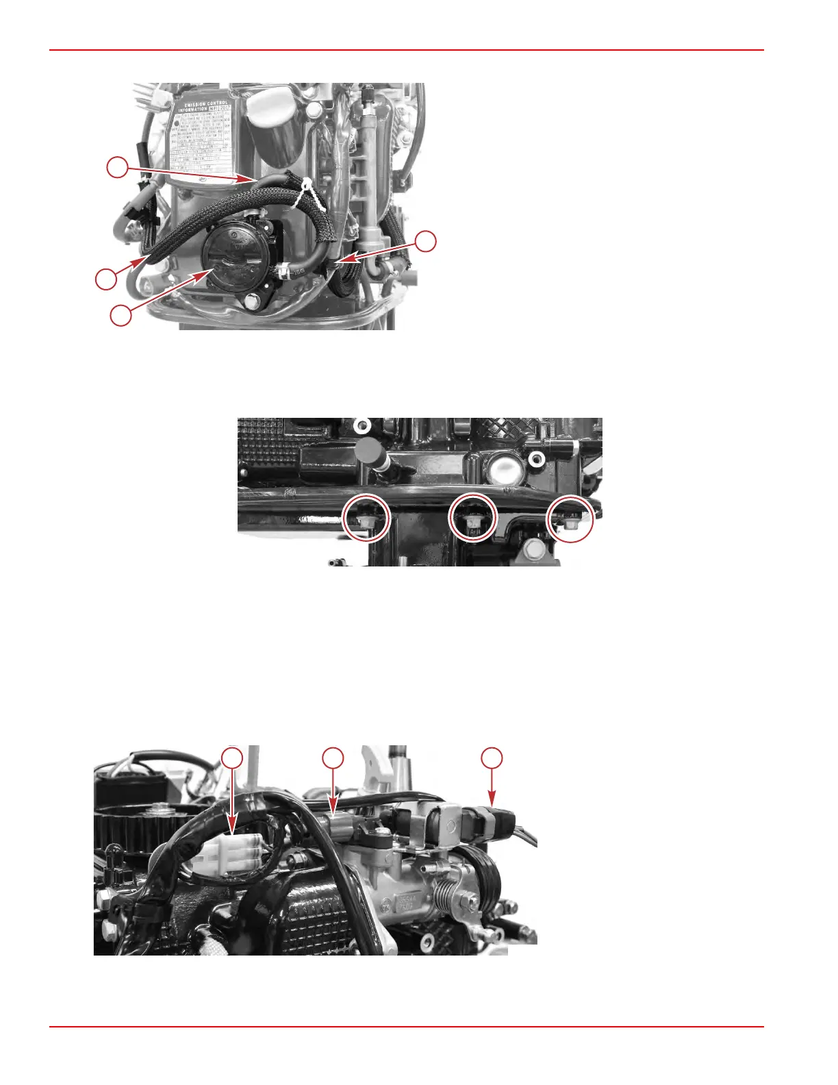
2. Disconnect the TPS, TMAP sensor, and IAC from the engine harness.
a - TPS connector
b - TMAP sensor connector
c - IAC connector
3.
Remove the ignition coil. Refer to Section 2A ‑ Ignition Coil.
4.
Disconnect the red bullet connector for the voltage regulator/rectifier (electric start models) and the 2‑pin connector for the
ECT sensor.
Cylinder Block/Crankcase
Page 4A-10 © 2018 Mercury Marine 90-8M0125265 eng NOVEMBER 2017
 Loading...