IGNITION SYSTEM
90-857138R1 MAY 2000 Page 2A-11
E. SURFACE INSULATION TEST - OPTIONAL
CAUTION
Complete this test as rapidly as possible, as it is a severe test on the coil.
1. Remove large red test lead from high tension spark plug lead.
2. Plug insulation test probe into “Probe Test” jack on analyzer.
3. Set analyzer to position 1. “Coil Power Test.”
4. Turn “Hi-Lo” current control knob to “Hi” position but DO NOT exceed meter range (4
amps).
IMPORTANT: DO NOT allow test probe to linger too long at any one point.
5. Pass insulation test probe over insulating surfaces of the ignition coil and high tension
leads.
6. If coil or high tension lead insulation is cracked, leaking or damaged, a steady spark dis-
charge will occur between the cracked or leaking surface and the test probe.
NOTE: A faint spark does not indicate damaged coil.
7. Turn current control knob fully counterclockwise and put selector switch in “off” position.
8. Replace ignition coil and leads if any surface is damaged.
CDI Unit
IMPORTANT: The CDI unit can only be tested satisfactorily using a volt meter (capa-
ble of measuring 400 volts DC or higher) and Direct Voltage Adaptor (91-99045), or
Multi-Meter/DVA Tester (91-99750). Follow instructions in test manual included with
DVA or Multi-Meter/DVA Tester.
Test
Selector Switch
Position
DVA Leads Volts (1)
@ 300 - 2000 RPM
RED BLACK
Ign. Coil Primary 400 VDC Ground BLACK/YELLOW 120 - 300
Charge Coil 400 VDC BLACK/RED Ground 150 - 325
Stop Circuit 400 VDC BROWN Ground 175 - 300
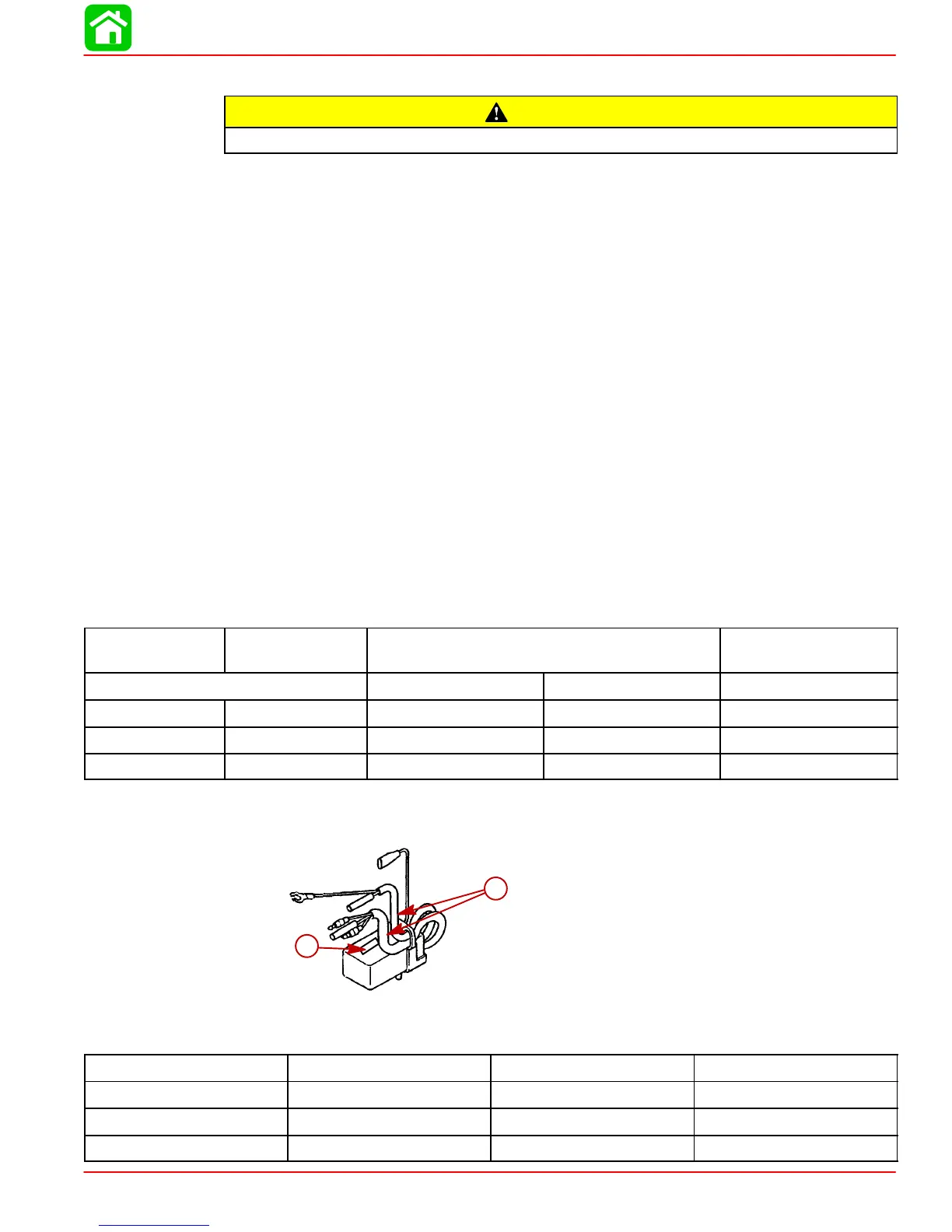
NOTE: 2000 model year outboards have model name stamped on surface top, Indicating
outer tube color, rev. limit (rpm), and ignition timing.
a
b
a-Model Name
b-Outer Tube
Model Name
Outer Tube Color Rev. Limit (rpm) Ignition Timing
CU2526 BLACK 5900 BTDC 5 - 25
CU2564 GRAY 5900 BTDC 25
CU2568 BLUE 6300 BTDC 25
 Loading...