WIRING DIAGRAMS
90-855347R1 JANUARY 1999 Page 2D-17
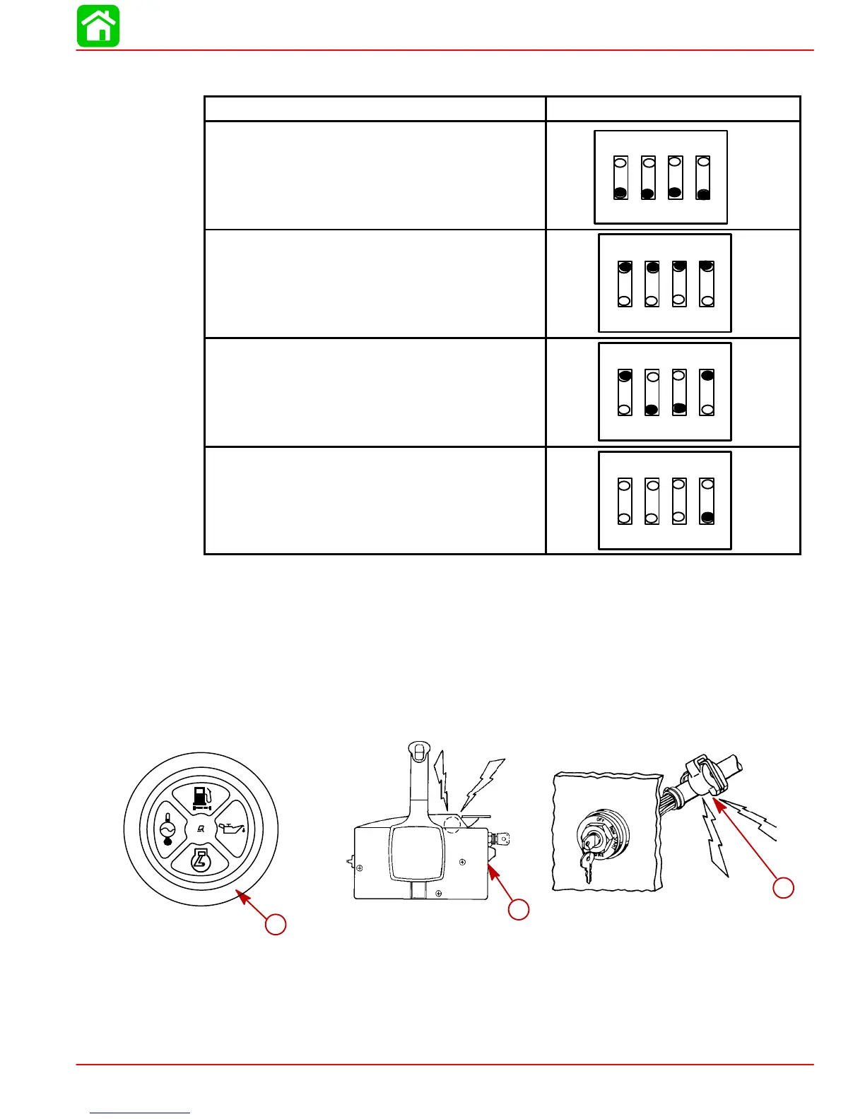
Outboard Multi-Function Gauge Setting
Model Dip Switch Setting
Test Display (All)
Open
1234
275 hp (3.4 Litre) Outboards (single engine)
Open
1234
135-250 hp Outboards (single engine)
Open
1234
“Note” On Dual Engine/Single Fuel Tank
Applications: Position Dip Switch 4 “Open”
*
Open
1234
* Dip Switch (4) in “Open Position” For Dual Engine Single Fuel Tank Applications.
Switches 1, 2, 3 Must Be In Specified Model Position.
Warning System
The outboard warning system incorporates warning light gauge (a) and warning horn (b).
The warning horn is located inside the remote control or is part of the ignition key switch
wiring harness.
a
b
b
a
b
b
When the key switch is turned to the ON position, the warning lights and horn will turn on
for a moment as a test to tell you the system is working.
 Loading...


