IGNITION
90-855347R1 JANUARY 1999 Page 2A-21
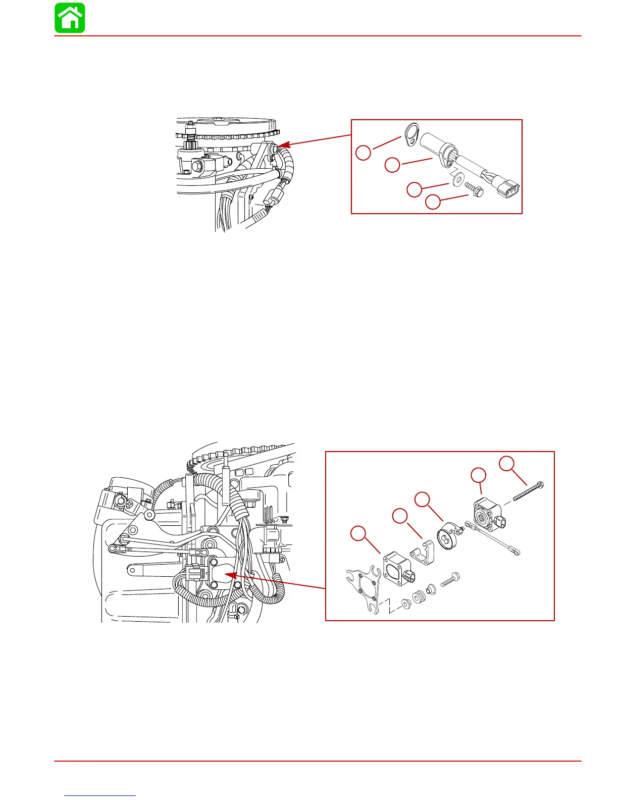
Crank Position Sensor
REMOVAL
1. Disconnect harness.
2. Remove bolt securing sensor to bracket.
56069
a
b
c
d
a-Shim (0.010 or 0.020 in.) (0.254 mm 0.508 mm)
b-Crank Position Sensor
c-Washer
d-Bolt – Torque to 50 lb-in (5.5 Nm)
INSTALLATION
1. Fasten sensor to bracket with bolt.
2. Set air gap @ 0.025 in. – 0.040 in. (0.635 mm – 1.01 mm)
3. Reconnect sensor harness.
Throttle Position Sensors (TPS)
REMOVAL
1. Disconnect wiring harness.
2. Remove screws securing sensors to bracket.
a
b
c
d
e
a
b
c
d
e
a-Throttle Sensor – Inside
b-Spacer
c-TPS Lever
d-Throttle Sensor – Outside
e-Screw (3) – Torque to 20 lb-in (2.5 Nm).
INSTALLATION
1. Fasten sensors to bracket as shown.
2. Reconnect wiring harness.