DIRECT FUEL INJECTION
Page 3B-26 90-855347R1 JANUARY 1999
Air Temperature Sensor Installation
Secure sensor in air plenum with 3 screws. Drive screws tight.
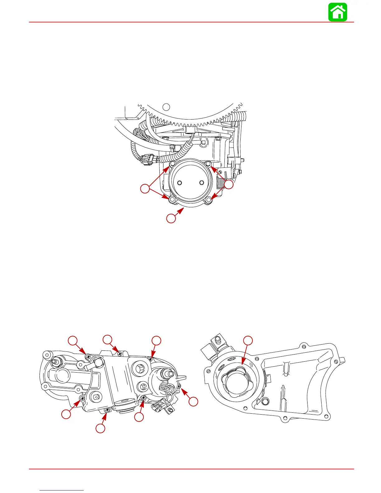
Throttle Plate Assembly Removal
NOTE: The throttle plate assembly is calibrated and preset for proper running character-
istics and emissions at the factory. Other than complete assembly removal from the air
plenum, no further disassembly should be made.
Remove 4 bolts securing throttle plate assembly to air plenum and remove assembly.
56068
b
a
a
a
b
a
a-Bolts
b-Throttle Plate Assembly
Throttle Plate Assembly Installation
Secure throttle plate assembly to air plenum with 4 bolts. Torque bolts to 100 lb. in. (11.5
Nm).
Vapor Separator Disassembly
1. Remove 7 screws securing separator cover and remove cover.
2. Inspect seal in fuel pump chamber of separator tank for cuts and abrasions. Replace
seal if necessary. If seal is serviceable, apply 2-4-C w/Teflon Marine Lubricant
(92-825407A12) to seal lips.
b
57342
a
a
a
a
a
a
a
57343
a-Screws (7 each)
b-Seal