CLAMP/SWIVEL BRACKETS & DRIVE SHAFT HOUSING
Page 5A-8 90-855347R1 JANUARY 1999
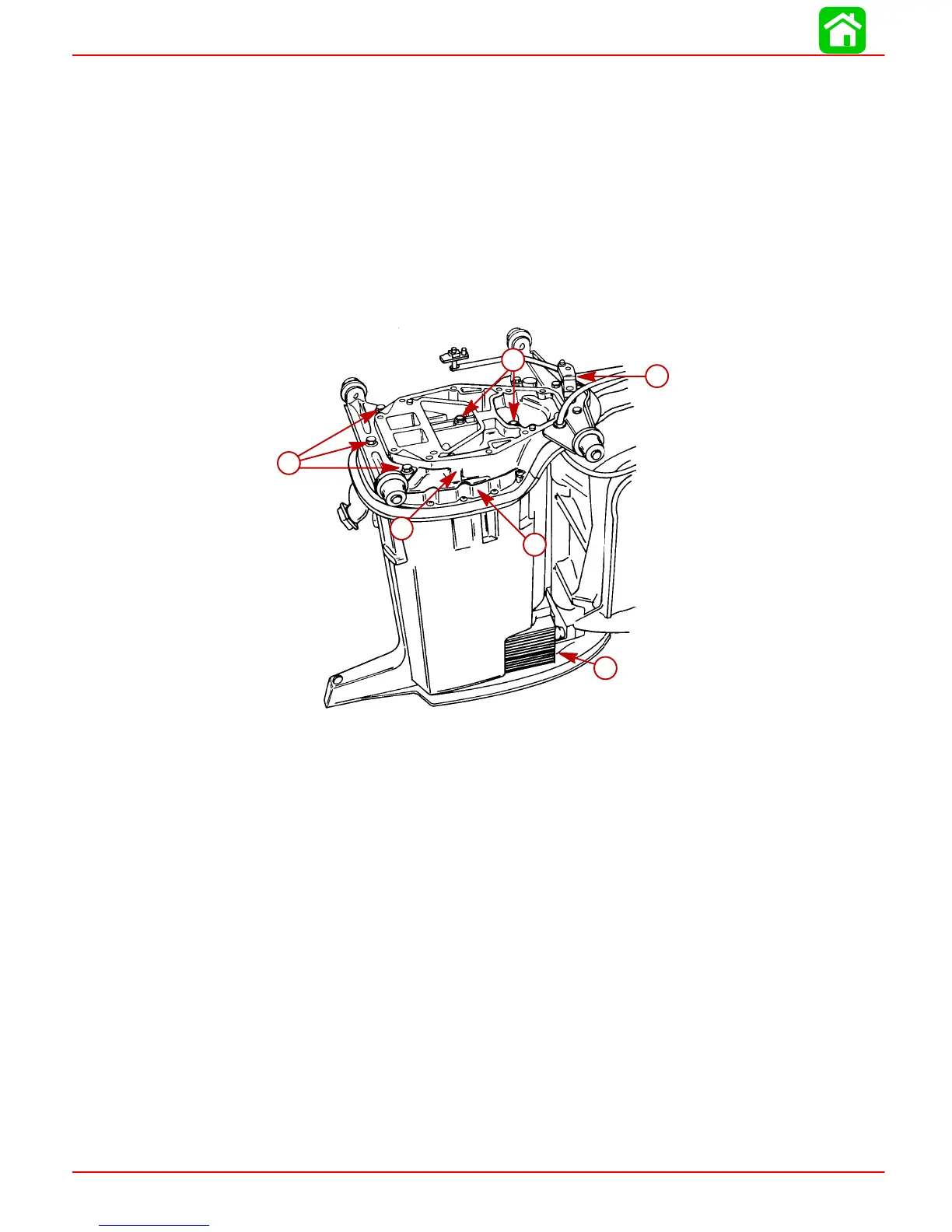
Drive Shaft Housing and Dyna-Float Suspension
Refer to “Powerhead Removal” section to remove powerhead. Refer to “Lower Unit
Removal” in this section to remove lower unit.
Removal and Disassembly
1. Remove shift shaft from driveshaft housing by pulling straight up on shaft.
2. Remove 5 bolts which secure exhaust extension plate to drive shaft housing. After
bolts are removed, lift exhaust extension plate off drive shaft housing.
3. Remove screws, which secure lower mount covers to drive shaft housing, then re-
move covers.
51858
a
b
c
d
e
f
a-Shift Shaft Linkage
b-Exhaust Extension Plate
c-Exhaust Plate to Drive Shaft Housing Bolts
d-Driveshaft Housing Plate
e-Lower Mount Cover (One Each Side)
f-Mounting Bracket Bolts