OIL INJECTION
90-855347R1 JANUARY 1999 Page 3C-11
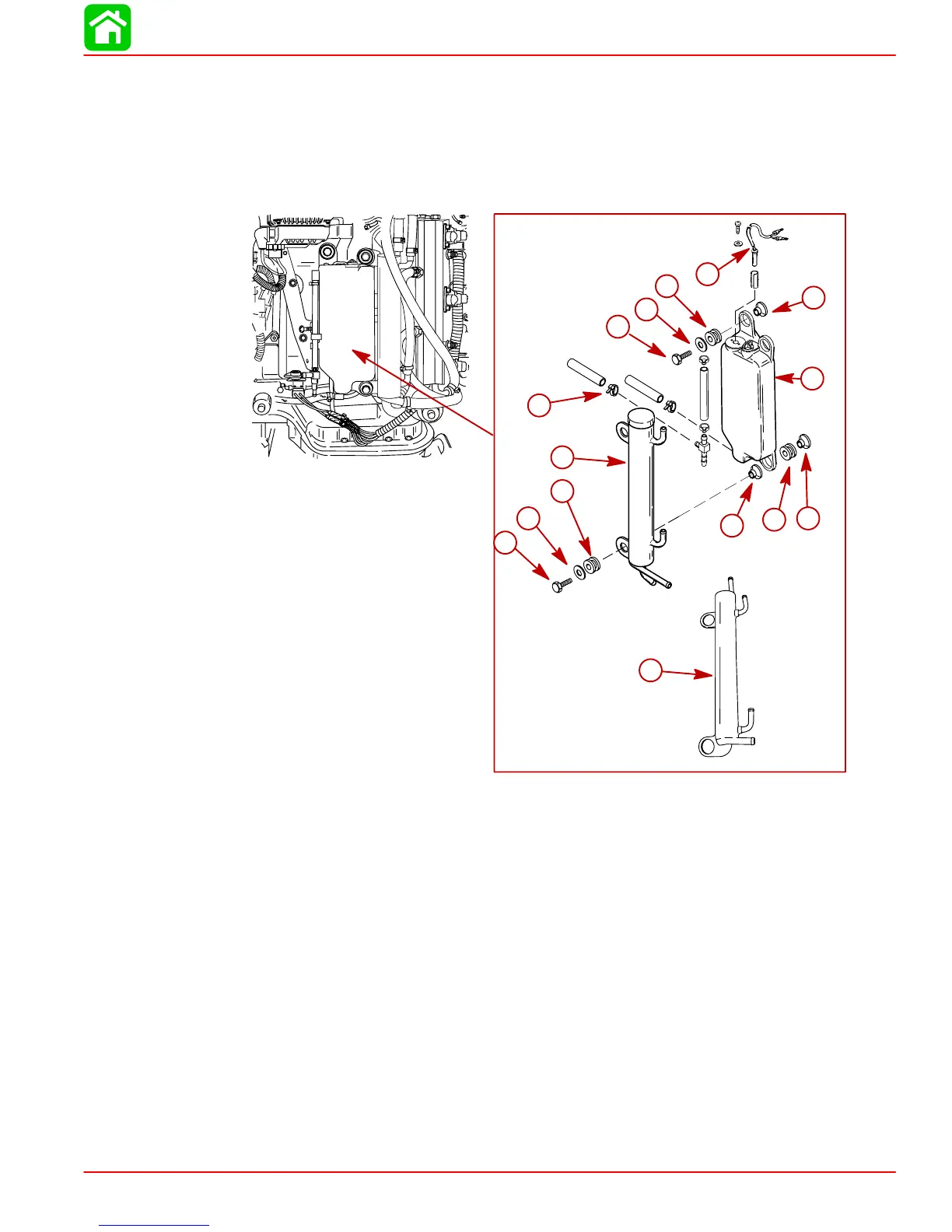
Engine Oil Reservoir Removal and Installation
REMOVAL
1. Disconnect the oil hoses. Plug the hoses to prevent spillage.
2. Disconnect the LIGHT BLUE wire leads.
3. Remove three bolts securing oil tank and fuel cooler to powerhead and remove tank.
a
b
c
d
e
f
g
h
i
j
d
e
g
g
k
a-Oil Reservoir
b-Fuel Cooler (Design 1)
c-Bolt (1) – Torque to 170 lb. in. (19 Nm)
d-Washer (3)
e-Rubber Grommet (3) – Insert into Holes
f-Low Oil Switch
g-Bushing (3)
h-Grommet (2) – Insert into Hole
i-Bolt (2) – Torque to 170 lb. in. (19 Nm)
j-Sta-Straps – Fasten All Hose Ends
k-Fuel Cooler (Design 2)
INSTALLATION
1. Install oil reservoir as shown.
2. Fasten the oil hoses with sta-straps.
3. Connect the LIGHT BLUE wire leads.
4. Refill the oil system. Refer to Priming the Oil Pump.