EasyManuals Logo

Mercury Optimax 150 User Manual

Mercury Optimax 150
522 pages
To Next Page IconTo Next Page
To Previous Page IconTo Previous Page
Page #243 background imageLoading...
Page #243 background image
POWERHEAD
Page 4A-20 90-855347R1 JANUARY 1999
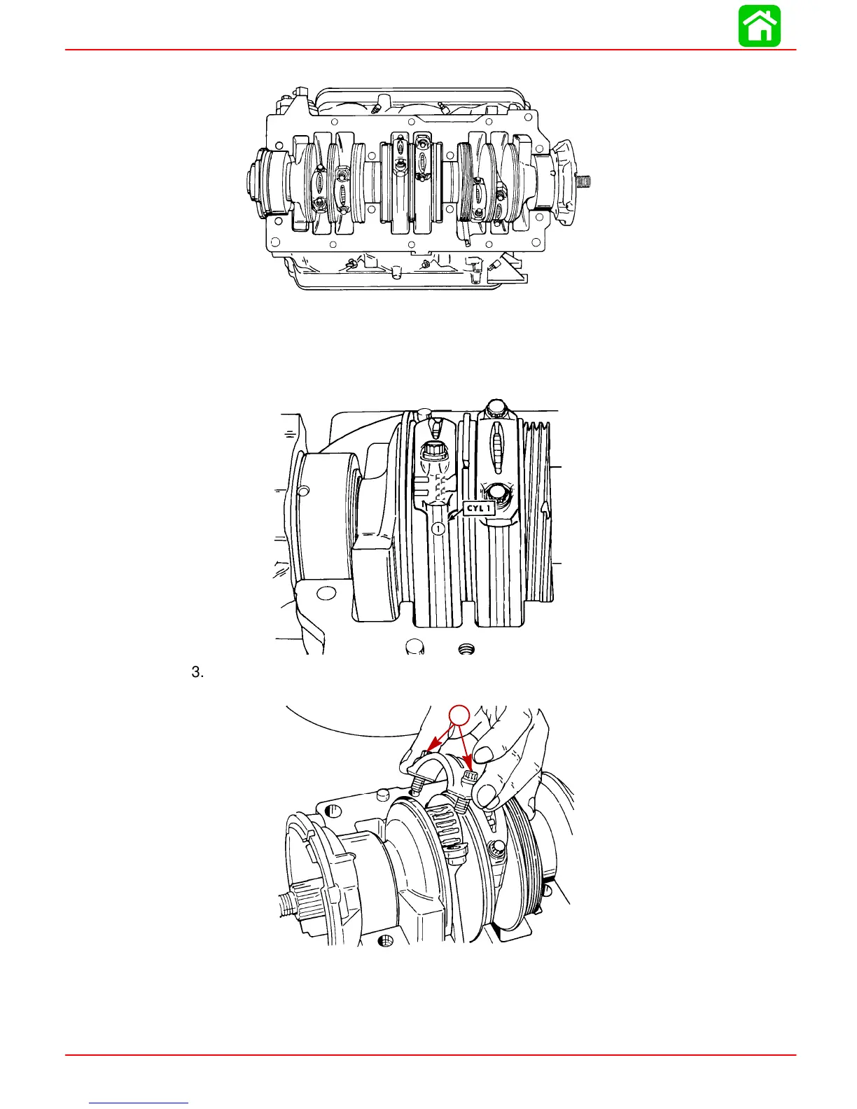
CRANKCASE COVER REMOVED
51848
1. Use Powerhead Stand (91-30591A1) for rotating crankshaft to desired position for re-
moval of connecting rods.
2. Using an awl or electric pencil, scribe the cylinder identification number on each con-
necting rod as shown. Reassemble connecting rods in same cylinder.
51849
Ä
Ä
3. Use a 5/16 in. 12 point socket to remove connecting rod bolts, then remove rod cap,
roller bearings and bearing cage from connecting rod.
51850
a
a-Connecting Rod Bolts
4. Push piston out of cylinder block.
5. After removal, reassemble each piston and connecting rod assembly.

Table of Contents

Questions and Answers:

Question and Answer IconNeed help?

Do you have a question about the Mercury Optimax 150 and is the answer not in the manual?

Mercury Optimax 150 Specifications

General IconGeneral
Horsepower150 HP
Engine TypeV6
Alternator Output60 amp / 756 watt
StartingElectric
SteeringRemote
Displacement2.5 L
Fuel Induction System2-Stage Direct Fuel Injection (DFI)
Shaft Length20", 25"
Dry Weight431 lbs (20 in), 439 lbs (25 in)

Related product manuals