POWER TRIM
90-855347R1 JANUARY 1999 Page 5B-19
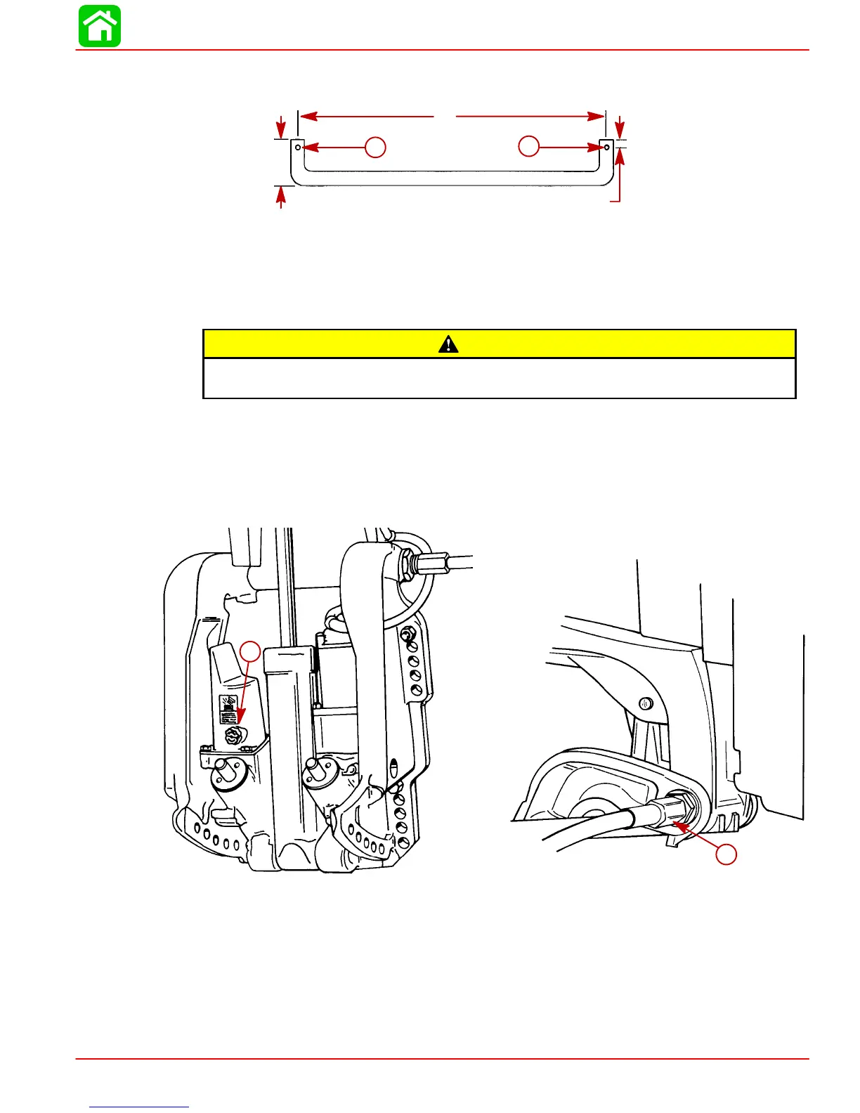
SUPPORT TOOL
3/8 in. diameter metal rod (a used shift shaft works well)
14”
2”
1/4”
a
a
a
a
a-Drill holes for retaining clips
METRIC CONVERSION
14 in. = 35.56 cm 2 in. = 50.8 mm
3/8 in. = 9.5 mm 1/4 in. = 6.35 mm
CAUTION
Disconnect battery cables at battery before removing power trim wires from sole-
noids.
3. Disconnect power trim wires at solenoids (BLUE, GREEN, and BLACK) or if relay
style, disconnect (BLUE and GREEN) bullet connector harness.
4. Open filler cap and release any remaining pressure in the system.
IMPORTANT: Outboards equipped with thru-the-tilt-tube steering - remove steer-
ing link arm from end of steering cable and cable retaining nut from tilt tube.
b
a
51339
51354
a-Filler Cap
b-Retaining Nut
 Loading...


