RIGHT HAND NON-RATCHETING
90-855347R1 JANUARY 1999 Page 6A-23
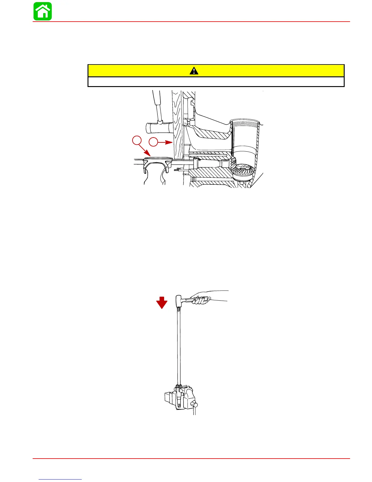
5. Remove gear housing from vise and re-position it as shown. Be sure to use soft jaw
vise covers and clamp as close as possible to water pump studs.
6. Place a block of wood on gear housing mating surface. Use a mallet and carefully tap
gear housing away from driveshaft.
CAUTION
DO NOT strike gear housing hard with the mallet or allow gear housing to fall.
51870
a
b
a-Wooden Block
b-Soft Jaw Vise Covers
7. Reach into gear housing and remove pinion gear and forward gear assembly.
8. After driveshaft is removed from gear case, remove and retain shim(s) that were lo-
cated under upper tapered driveshaft bearing.
9. If inspection determines that replacement of driveshaft tapered bearing is required,
remove bearing from driveshaft as follows:
a. Position driveshaft in a vise; DO NOT tighten vise jaws against shaft.
b. Strike shaft with a lead hammer; take care not to drop shaft.
51866
10. Remove 18 loose needles from outer race of driveshaft needle bearing.
11. If inspection of driveshaft needle bearing surface determines that replacement of
needle bearing is required, the 18 loose needle bearings previously removed must
be reinstalled in bearing race to provide surface for mandrel to drive against.
 Loading...


