36
The EtherNet/IP Electrical Connection can be used to connect the EB 80 system to a EtherNet/IP network. In compliance with current specifications,
the ODVA offers diagnostic functions and is available in the configuration up to 128 outputs for solenoid pilots, 128 digital outputs, 128 digital
inputs, 16 analogue outputs, 16 analogue inputs and 16 analogue inputs for temperatures.
INTENDED USE
This manual is intended exclusively for technicians qualified in control and automation technology, who have acquired experience in installing,
commissioning, programming and diagnosing programmable logic controllers (PLC) and Fieldbus systems.
TARGET GROUP
1. INSTALLATION
WARNING
The EB 80 EtherNet/IP must only be used as follows:
• as designated in industrial applications.;
• in systems fully assembled and in perfect working order;
• in compliance with the maximum values specified for electrical ratings, pressures and temperatures.
• Only use power supply complying with IEC 742/EN60742/VDE0551 with at least 4kV insulation resistance (PELV).
1.1 GENERAL INSTRUCTIONS FOR INSTALLATION
Before carrying out any installation or maintenance work, switch off the following:
• compressed air supply;
• the operating power supply to solenoid valve / output control electronics.
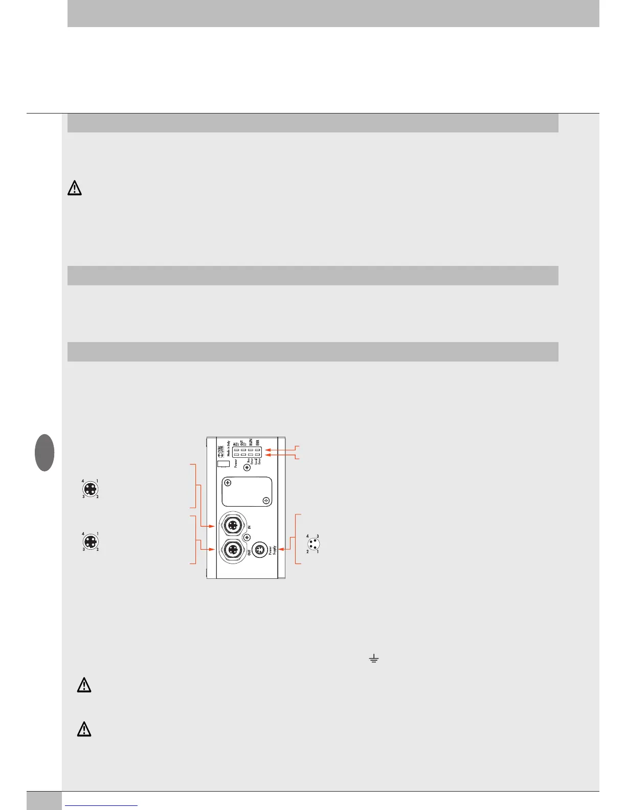
1.2 ELECTRICAL CONNECTION AND DISPLAY ELEMENTS
EtherNet/IP
diagnostic signaling LED
EB 80 Net diagnostic signaling LED
Connection to the EtherNet/IP network
Power Supply (M8 male connector)
IN ( (M12 Female Connector, D encoding)
OUT (M12 Female Connector, D encoding)
1 = TD+
2 = RD+
3 = TD-
4 = RD-
Metal ring nut = Shield
1 = TD+
2 = RD+
3 = TD-
4 = RD-
Metal ring nut = Shield
1 = +24V bus (Brown)
2 = +24V valvole (White)
3 = GND (Blue)
4 = GND (
Black
)
Connection for node power supply and
auxiliary valve power supply
WARNING
Failure to make the earth connection may cause faults and irrevocable damages in the event of electrostatic discharge.
In order to guarantee IP65 protection class, any discharge must be conveyed and unused M12 connections must be provided with a protective cap.
1.3 ELECTRICAL CONNECTIONS: PIN ASSIGNMENT OF CONNECTOR
1.3.1 M8 connector for node and output power supply
1 = +24V Connector for node EtherNet/IP and input/output power supply
2 = +24V Auxiliary valve power supply
3 = GND
4 = GND
The EB 80 must be earthed using the end plate connection marked with the symbol PE
WARNING
The bus supply system also powers all the Signal modules S that are directly connected to the node; the maximum supplied current is 3.5 A.
GB