Page 18 of 48
3.1 Connecting the System
The Energiser should be connected to an appropriate 3 phase power
supply by a competent qualified electrician in accordance with the
following recommendations:
Position the Energiser to allow unrestricted airflow into / out of the unit and
connect to a mains isolator fuse box ensuring each phase carries suitable
fuses.
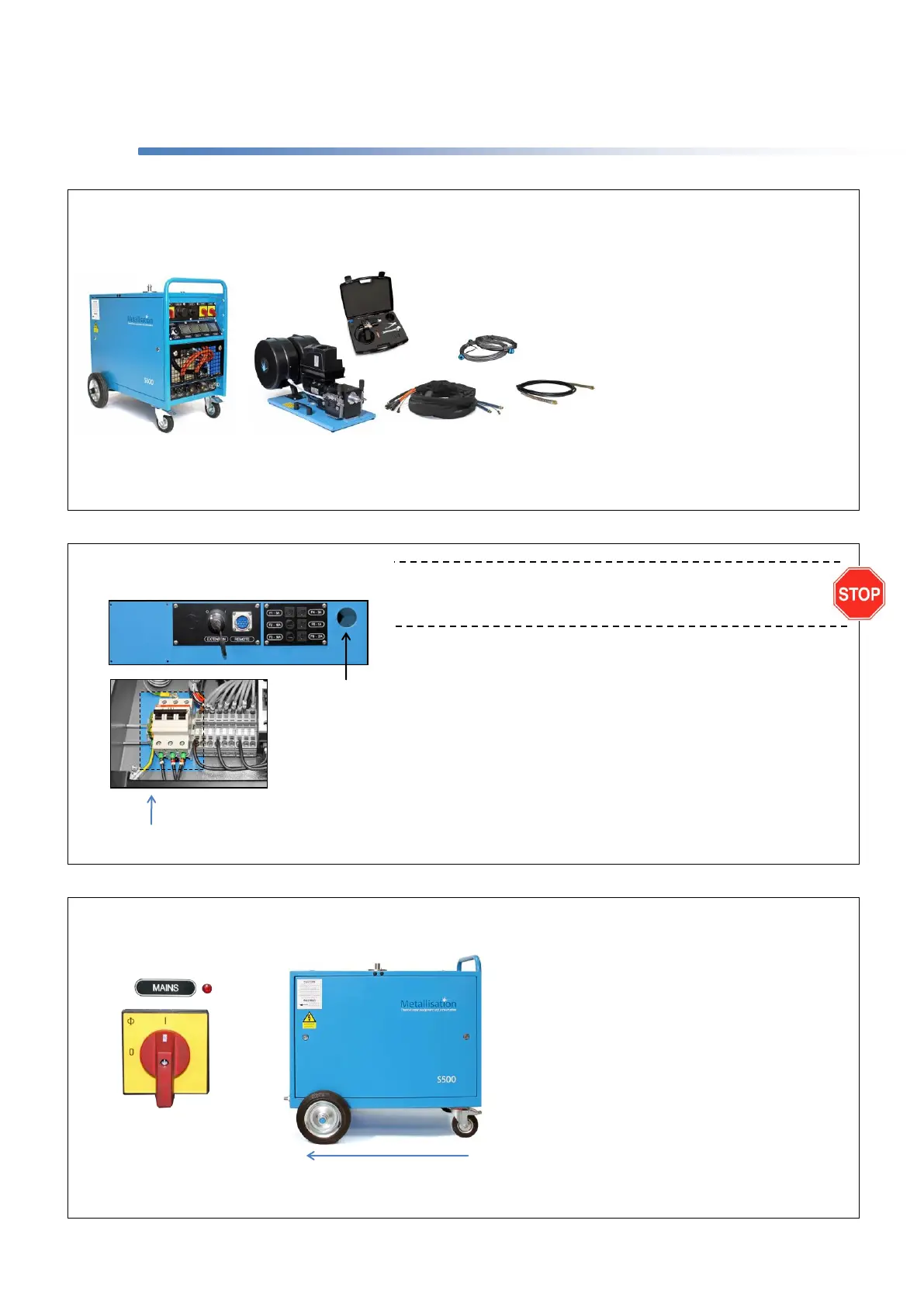
Remove the top panel and connect a suitable Power Cable to terminals 1, 2,
3 and Earth.
Check that the input voltage is correct for the unit (Refer to Energiser
Maintenance Manual).
Connect suitable size hose to the air supply. It is strongly recommended that
a filter unit be installed at the mains outlet point. A capacity of 1.5m³ /min @
5 bar (53cfm @ 72.5 psi) is usually adequate.
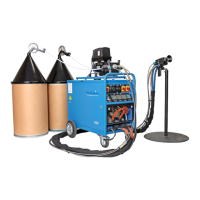
Remove any packing materials and ensure that all items are present and the equipment has suffered no damage whilst in transit
(see conditions of sale). NB: if using long supplies with a powered extension trolley also refer to Section 3.2.
A. S500-PLC Energiser.
B. Drive Unit Assembly.
C. Power Cable / Air Hose Assembly.
D. Wire Feed Conduits.
E. Flexible Drive Cable.
F. ARC150 Pistol and Tool Case.
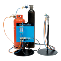
Switch on Power Supply and turn the Mains
Switch on.
Cooling Airflow should pass from front to
back. If air passes from the back to the front
of the Energiser, the fan is running in
reverse.
If this is allowed to continue damage to the
Energiser may occur. Isolate the Power
Supply and reverse two phases of the
input 3 phase.
Once airflow is passing through correctly,
turn the Mains Switch off and refit all panels.
Feed Power
Cable through
opening using a
suitable Gland