Preparation for use | EN
15
5.4. Electronics
Themainsconnectionmayonlybecarriedoutbyaqualiedelectrician.Theelectricalinstallationmustbecarriedoutinaccordancewiththeapplicablelocal
regulations.Beforeconnectingtothemains,comparetheratedvoltageonthedevicetypeplatewiththemainsvoltage.
Main switch:
Itmustbeensuredthatthepowersupplyisconnectedafterthedevice/practicemainswitch.
Danger:
The supply voltage must be taken from a safety transformer that meets the requirements of EN 60601-1 and EN 61558-2-6.
Danger:
Fuses may only be replaced by the same type!
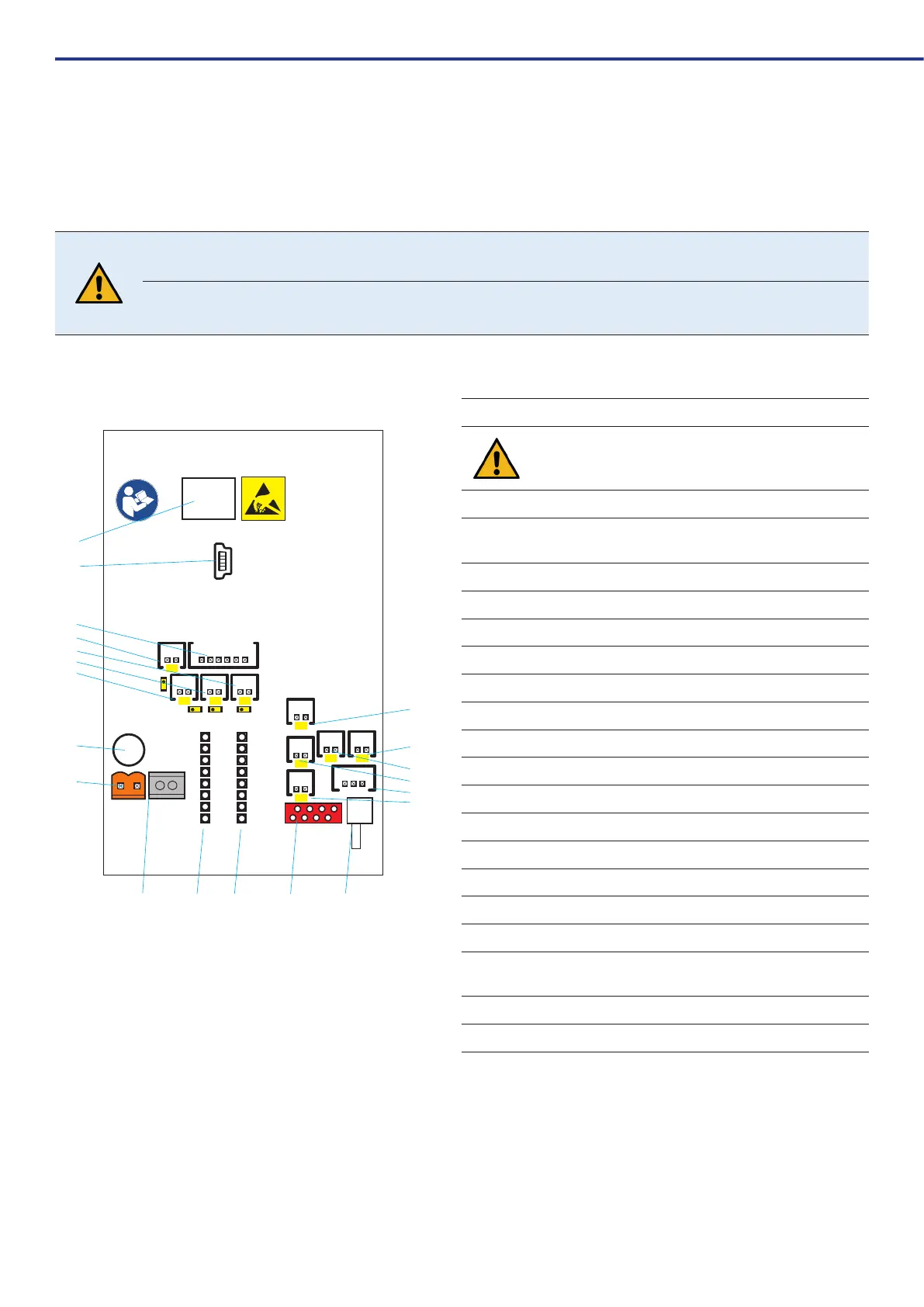
5.4.1. Electrical connections / circuit diagram
24V~
X1
MOT
X2
SIC1
T 1,6 A
X12
200003193v03 | 2024-01
USB
MINI-B
X10
METASYS WEK
X11
X3
X5
X18
X23
X24
X25
X22
X16
X13
X6 X4 X7
LED1
LED3
LED2
LED4
BATT
2x LR44
1,5 V
IC3
3
4
2 1
0
87
6
9
18
1
2 11
3
5
7
4
6
20
8
19
10 9
13
14
12
15
16
17
1 X1-Powersupply24VAC(orange)
The supply voltage must be taken from a safety transformer that
meets the requirements of EN 60601-1 and EN 61558-2-6.
2 X2 - Pump motor connection
3 X3-Aircushionmagneticvalveonthepressuretank(MV4,
LED1)
4 X4-Compressedairmagneticvalve(MV3,LED3)
5 X5 - External display
6 X6-Magneticvalvedisinfectant(MV2,LED2)
7 X7-Magneticvalvewaterinlet(MV1,LED4)
8 X10 - USB Mini-B connection
9 No function
10 No function
11 No function
12 X16 - SP1+2 Fill level in mixing container
13 X18-Pressureswitchpressuretank
14 X22 - SP3 Level sensor on pressure tank
15 X23-SP4Overowprobemixingcontainer
16 X24 - SP5 Disinfectant sensor
17 X25 - SP6 membrane rupture sensor
18
Main fuse MST 1.6 A/ UN 250V
(Fusesmayonlybereplacedbythesametype!)
19 Back-up battery 2x LR44 1.5 V
20 IC3 - No function