MI 3125 / MI 3125E EurotestCOMBO Start-up guide
5
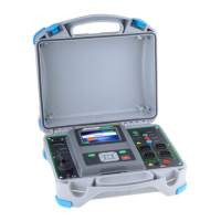
1.2 Instrument description - Front and connector panel
8
9
10
11
12
7
6
5
4
3
2
1
Instrument description
1. Display
2. TEST button
3. Arrow key
4. Arrow key
5. CAL button (for zeroing out leads,
measuring Zref)
6. Function Selector
7. Backlight button
8. On/off button
9. HELP button
10. TAB button (for changing test
parameters)
11. Pass indicator
12. Fail indicator
1
23
4
Connectors
1. Test lead socket
2. Cover
3. Charger socket
4. RS232 (serial)
connector
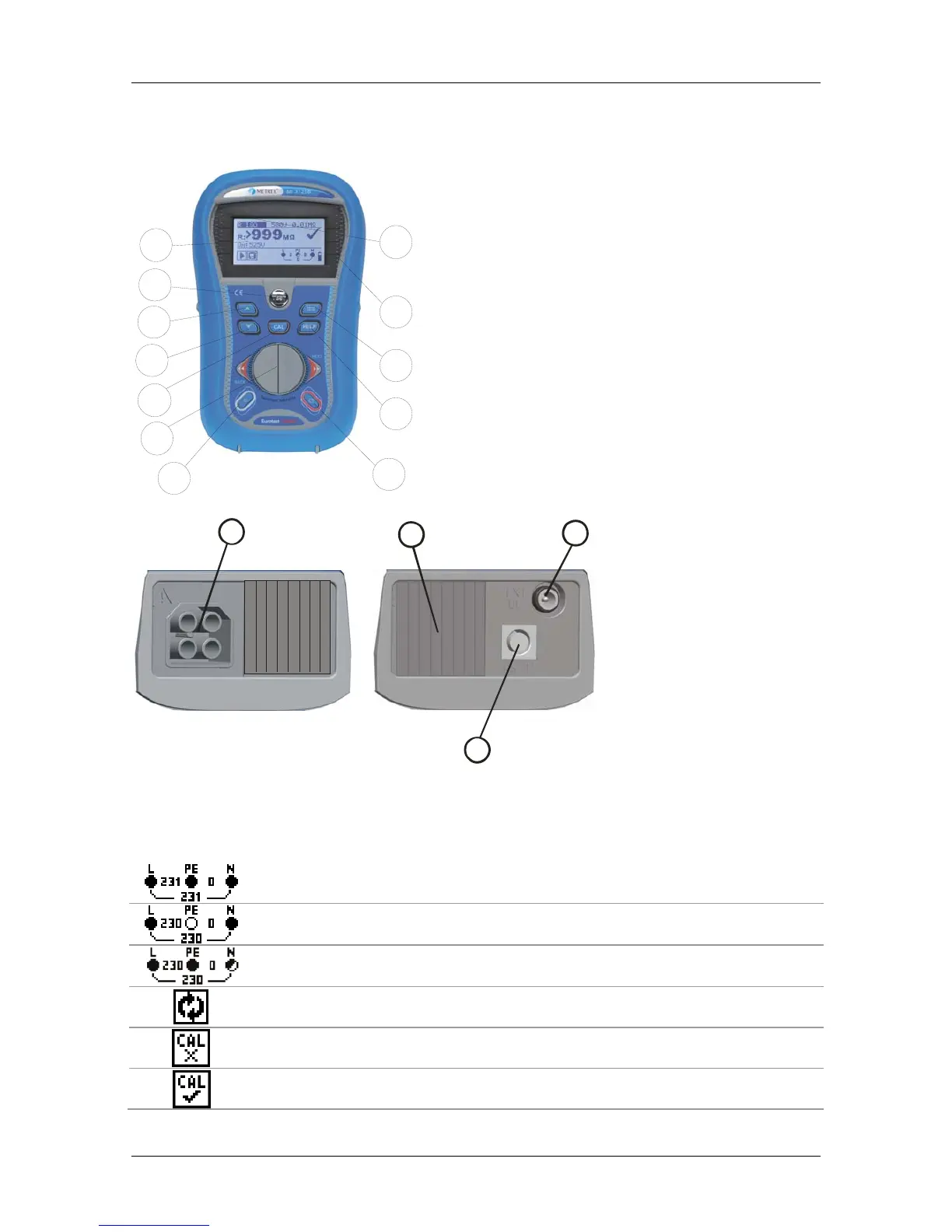
1.3 Instrument description - Meaning of symbols
The online voltage and output terminal monitor
Online voltage is displayed together with test terminal indication. All
three test terminals are used for selected measurement.
Online voltage is displayed together with test terminal indication. L and
N test terminals are used for selected measurement.
L and PE are active test terminals; N terminal should also be connected
for correct input voltage condition.
L – N polarity changed.
Test leads resistance in Continuity measurement is not compensated.
Test leads resistance in Continuity measurement is compensated.

 Loading...