■■■■■■■■■■■■■■■■■■■■■■
Table of figures
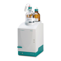
904 Titrando
■■■■■■■■
V
Table of figures
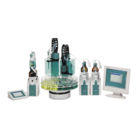
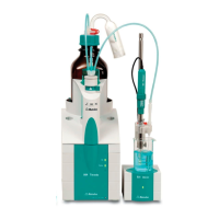
Figure 1 The Titrando system .......................................................................... 1
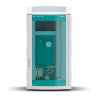
Figure 2 Front 904 Titrando ............................................................................ 8
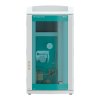
Figure 3 Rear 904 Titrando ............................................................................. 9
Figure 4 Connecting the Touch Control ......................................................... 11
Figure 5 Connecting the computer ................................................................ 14
Figure 6 MSB connections ............................................................................ 15
Figure 7 Connecting a dosing device ............................................................. 17
Figure 8 Connecting an MSB stirrer ............................................................... 18
Figure 9 Connecting the rod stirrer to the titration stand ............................... 18
Figure 10 Connecting the Remote Box ............................................................ 19
Figure 11 Connecting a printer ....................................................................... 21
Figure 12 Connecting a pH, metal or ion-selective electrode ........................... 24
Figure 13 Connecting a reference electrode .................................................... 25
Figure 14 Connecting a polarizable electrode .................................................. 25
Figure 15 Connecting a temperature sensor or an electrode with integrated tem-
perature sensor ............................................................................... 26
Figure 16 Connecting the iConnect ................................................................. 27
Figure 17 Connecting an electrode to the iConnect ........................................ 27
Figure 18 Schematic configuration of magnetic stirrer, electrode and buret tip
during a titration. a) stirring direction clockwise, b) stirring direction
counterclockwise. ............................................................................ 29
Figure 19 Attaching the exchange unit ............................................................ 30
Figure 20 Connectors of the Remote Box ........................................................ 36
Figure 21 Pin assignment of remote socket and remote plug ........................... 36
 Loading...