8. POSITION FEEDBACK AND STATUS
INDICATORS
8.1 Position Feedback
The Position Feedback provides an analog indication of the
actuator output position scaled between the configured
Zero and Span positions.
Figure 13
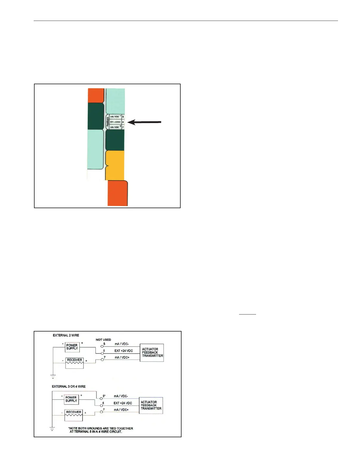
8.1.1 4-20mA
The 4-20mA Feedback can be powered either internally (by
the actuator) or externally (by the loop).
If the Position Feedback will be powered internally, connect
as follows: NEG to terminal 5; POS to terminal 7.
If the Position Feedback will be powered externally, it is
extremely important to terminate the customer supplied
+24VDC to the correct terminal on the Universal Control
Board. The Position Feedback switches are also important.
The Power Switch should be down in the “Ext” position
and the Signal Switch should be down into the “4-20mA”
position. (See Figure 14 for wiring options).
Figure 14
The 4-20mA Feedback circuit will power down if no
impedance is measured on the output terminals in both
Normal and Energy Save Mode operation. This is to stop any
unnecessary power drain while the 4-20mA feedback circuit
is not connected. Keep the metering circuit connected to
ensure that the feedback will be available as needed. If the
actuator position changes and there is a metering circuit
connected, then the feedback circuit will resume operation
and track the position.
8.1.2 0-10VDC
The 0-10V Feedback can only be used with internally (by
the actuator) supplied power.
The Position Feedback switches are also important. The
Power Switch should be up into the “Int” position and the
Signal Switch should be up into the “0-10V” position.
8.2 Status Indicators
8.2.1 Auxiliary Switches
Two auxiliary limit switches will provide position indication
for customer use. The switches are dry contacts that can
be used to operate other devices. Switches are single pole,
double throw; rated for 11A, 1/2HP, 250VAC, CSA certified.
8.2.2 Power Status Relay
The Power Status Relay is “high” if external voltage (12-
24VDC, 24VAC power inputs to the board and the output
from the Switching Power Supply to the board) is greater
than 12.5V. The relay is “low” if external voltage drops
below 10.5V and will alternate between “high” and “low” if
the motor is stalled.
8.2.3 Battery Status Relay
The Battery Status Relay is “high” if battery is present (Vbat
>= 6V) and fully charged (Charger current is <10mA); if
the relay switches to “low” the back-up battery should be
checked/replaced. NOTE: After a loss of external power,
the Battery Status Relay may show “low” for a period of time
while the battery is charging.
9. POWER MANAGEMENT
9.1 Battery
With the optional battery backup (included with options
UL2, UL3, UL4, UL5, UL6 & UL7), the actuator will sense the
loss of main input power to the Universal Control Board
and immediately switch to internal battery power. When
line power returns, the actuator will automatically resume
normal operation.
The battery charging voltage has been designed for
optimum battery performance. When the charging circuit
is active (even when topping off charge or in sleep mode),
the yellow Charging LED will light. After reaching full
charge, the green Charged LED will light. *Fully charged,
the battery voltage will reach approximately 13.6 volts.
IMO 6/18
IMO-I4900 EN 13

 Loading...


