Remove the three Philips head screws that hold the
VCB00010 Board in place with the #1 Philips screwdriver,
and save them for later use.
Figure 18
Unplug all cables attached to the VCB00010 and remove
the board. Connections are coded to prevent miswiring.
12. BOARD INSTALLATION
12.1 Step by Step Instructions for the
Installation of a Universal ADC/LADC-
Series Actuator Control Board:
Figure 19
Prior to installation, ensure that all switch an potentiometer
settings on the replacement board match that of the
original board.
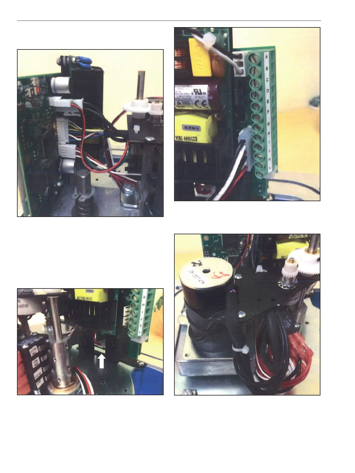
Connect the lower power supply cable to the VCB00010.
Connect the potentiometer, thermal cut-out, motor harness,
and limit switches; as shown in Figure 18.
Figure 20
Connect the upper power supply cable and the auxiliary
limit switch cables as shown in Figure 20.
Figure 21
Secure wires as shown in Figures 18 and 21 to avoid
contact with moving parts.
Re-install the three screws that secure the VCB00010 board
to the bracket as shown in Figure 17.
IMO 6/18
16 IMO-I4900 EN

 Loading...


