4.4.2 Cam Limit
When “Cam” is selected as the limit type, two limit switches
operated by the stainless steel cams on the output shaft
extension are used to determine the exact positions where
the actuator will stop at each end of CW and CCW travel. The
bottom limit switch determines the clockwise stop position.
The next limit switch, up from the bottom determines the
counter-clockwise stop position. The “end of travel limit”
switches can be adjusted to provide from 5 to 320 degrees
of actuator rotation. For “Three-Position” operation, limits
must be entered and saved using the “Smart” Limit!
4.5 Built-In Heater/Thermostat Feature
The Universal Control Board is equipped with a built-in
Heater/Thermostat Option that can be enabled for low-
temperature use (environments where the temperature will
drop below 32° Fahrenheit), high-humidity use (“tropical”
environments), or disabled completely to conserve power, in
environments where the climate is stable and/or controlled.
NOTE: All heater modes are disabled in “Energy Save” mode.
The Heater/Thermostat is enabled/disabled by sliding a
switch on the Universal Control Board. See graphic below
for proper positioning:
Figure 6
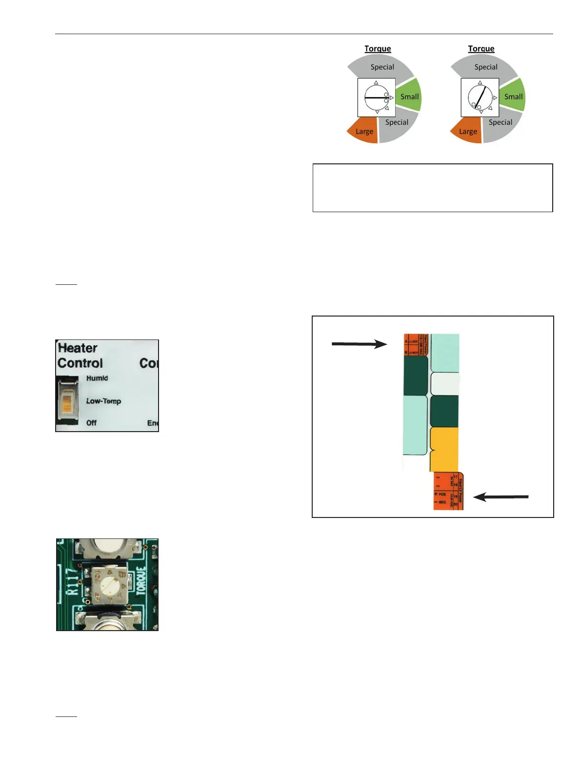
4.6 Torque Limit
The actuator is equipped with a torque limit feature; see
Figure 7 for identification of the torque setting potentiometer
(located under the overlay, between the CW and CCW
pushbuttons).
Figure 7
There are two standard settings as follows:
“Small” actuator; 150, 300, or 600 lb-in torque rating.
“Large” actuator; 1000, 1500, 2000, 2500, or 3000 lb-in
torque rating.
NOTE: The sections marked “Special” will be utilized only by the factory
to limit the torque output to a value below the actuator’s maximum rated
torque.
WARNING
FAILURE TO SET THE TORQUE VALUE IN THE APPROPRIATE REGION
FOR THE ACTUATOR SIZE WILL VOID THE PRODUCT WARRANTY.
5. MAIN ACTUATOR POWER
The identication label on each actuator species the
model number, serial number, actuator power voltage and
current requirements for the actuator. It is important to
verify the correct actuator voltage and control voltage
prior to wiring the actuator.
Figure 8
5.1 115VAC or 230VAC Power Wiring
If using 115VAC or 230VAC as the MAIN Input Power:
115/230 VAC must be supplied constantly to the Universal
Control Board as follows:
- Terminal A (AC L1/HOT)
- Terminal B (AC L2/NEUT)
5.2 24VAC Power Wiring
If using 24VAC as the MAIN Input Power: 24VAC must be
supplied constantly to the Universal Control Board as follows:
- Terminal 17 (24AC HOT)
- Terminal 18 (24AC NEUT)
IMO 6/18
IMO-I4900 EN 7

 Loading...


