Set SPAN (typically CCW):
1. Turn the Mode Selector Dial to [SPAN] and press [ENTER]
for 2 seconds. The [SPAN] LED will begin to flash.
2. Drive the actuator to desired counterclockwise position
using the CW or CCW push button. If the “STALL” LED
begins to flash; check to see if the limit switch cam is
preventing actuator from reaching desired SPAN end-
of-travel (the “Switch Trip” LED will be illuminated).
If necessary, back the cam off so that it will trip the
switch slightly beyond the desired end-of-travel and
the “Switch Trip” LED will go out.
3. Press the [ENTER] button to save the SPAN setting.
6.3.4 Verify End-Of-Travel Settings:
1. Turn the Mode Selector Dial to [RUN].
2. Apply various control signals to verify operation.
3.
Verify that the “Switch Trip” LED is not illuminated at either
the ZERO or SPAN positions (if it is, “back” the respective
end-of-travel cam “off” of the respective limit switch).
4. Replace actuator cover.
6.3.5 Proper Actuator Cover Replacement
NOTE: For actuators including hazardous location certica-
tion. Prior to installing cover, inspect machined ange surfaces
for any damage, scratches, or dents. Damage, scratches, or
dents that will not t completely in a circle having a diam-
eter of 1/64” will void hazardous location certications. If such
imperfections are present the damaged enclosure parts(s)
must be replaced. Consult the factory for replacement parts.
1. Remove the override shaft from the actuator cover
bushing; if the actuator is equipped with a handwheel,
remove the handwheel before removing the top piece
of the “two-piece” shaft from the cover bushing.
2. Install the override shaft on the square motor shaft; if
the actuator is equipped with a handwheel, install the
bottom piece of the “two-piece” shaft on the motor
shaft and then install the top piece of the shaft onto
the bottom piece of the shaft.
3. Align cover so that the override shaft will pass through
the override bushing and carefully push it down so
that the cover flange contacts the base flange.
4. Once the cover is properly seated, tighten the screws
to secure the cover; a cross pattern is recommended
for uniform distribution of load.
5. If the position indicator is not seated to the output/
cam shaft, turn until it drops into place in order to
ensure accurate visual position indication.
7. POSITION CONTROL See Figure 5
7.1 The three methods of Position Control
The Position Control mode allows the actuator to modulate
(change position) in response to a change in an analog or
resistance control signal. The different modes are as follows:
7.1.1 “4-20mA Current Analog” Control
The actuator will modulate between positions in direct
response to the change in the input current signal. Set 4 mA
as the Zero position and 20mA as Span for normal operation
or set 4mA as Span and 20mA as Zero for reverse acting.
7.1.2 “0-10VDC Voltage Analog” Control
The actuator will modulate between positions in direct
response to the change in the input voltage signal. Set
0VDC as the Zero position and 10VDC as Span for normal
operation or set 0VDC as Span and 10VDC as Zero for
reverse acting.
7.1.3 “Resistive” Control (up to 10K Ohm)
The actuator will modulate between positions in direct
response to the change in the input resistive signal.
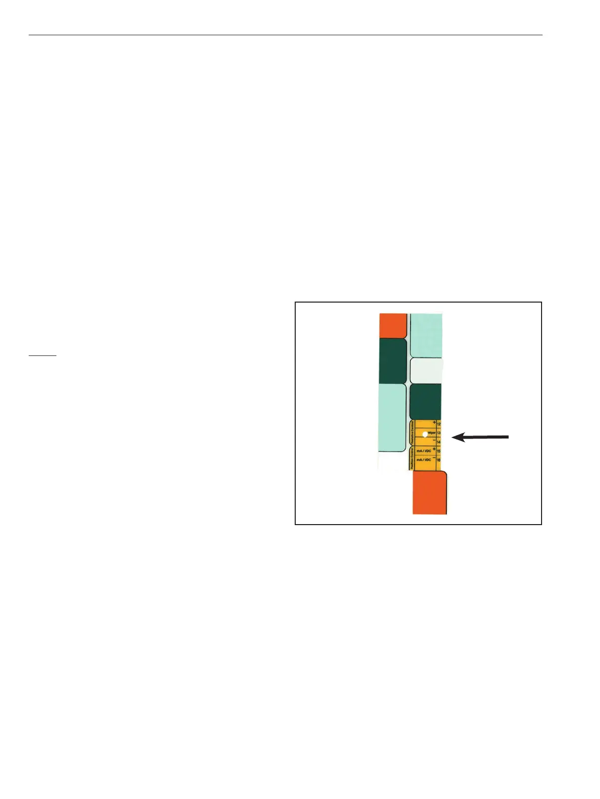
7.2 Position Control Signal Wiring
Figure 11
7.2.1 Analog Control Wiring
To control the actuator with a 4-20mA or 0-10V analog
signal: Connect mA / VDC - (NEG) to terminal 16 and mA /
VDC + (POS) to terminal 15 on the Universal Control Board
Slide the [Input] switch up to select 0-10V or down to select
4-20mA.
7.2.2 Resistive Control Wiring
To control the actuator with a resistance signal such as 0-
135 Ohms: Connect Resistance Signal - (NEG) to terminal
14, Resistance Signal Wiper to terminal 13, and Resistance
+ (POS) to terminal 12 on the Universal Control Board. The
board will respond to resistance signals up to 10K Ohms
(minimum SPAN signal is 100 Ohms; i.e. signal = 0-100 Ohms).
IMO 6/18
10 IMO-I4900 EN

 Loading...


