1 GENERAL
1.1 Description
The V-Series Iso/Readback Board is a 115/230 VAC option
that provides jogging or latching control from a low voltage
(12 VDC or 24 VDC) or high voltage (115 VAC or 230 VAC)
control signal. It also provides:
• a 4-20 mA or 0-10 DC position “readback” signal
• isolation for the motor, so that multiple actuators may
be wired in parallel
• supervisory control via a mode selector switch and
on-board CW and CCW push buttons.The supervisory
control mode overrides a remote signal for simple and
uninterrupted system set-up.
The isolation feature solves the problem of feedback
voltage interfering with PLC or DCS systems. In standard
electric actuators, the motor acts as an inductive load and
"steps up” the input voltage, and feeds it back via the non-
powered terminals to the power supply. The Iso/Readback
board isolates the motor from the control signal,preventing
the feedback voltage from reaching the power supply.
Position indication is available at terminals 5 and 6 on the
Motor Board (for discrete end of travel indication), and at
terminals D and E on the Iso/Readback Board (for analog
position readback).
Note:This option will fit all V-Series 115 & 230 VAC actuators
with the letter “N” preceding the voltage designator in the
part number on the product nameplate.
1.2 Operation
1.2.1 High or Low Voltage Control Signal
The Iso/Readback Board plugs into the Valvcon Motor Board
using standard brackets and mounting screws provided
(see Section 2.2 Installation Instructions if necessary).
Several selector switches are provided on the board for
mode set-up. The matrix below explains the actuator’s
functions for each combination of switch settings:
1.2.2 Position Readback
The Iso/Readback Board provides either a 4-20 mA or 0-10
VDC analog signal for position indication. To initiate this
function, connect to terminals D and E on the Iso/Readback
Board.Then:
1. Calibrate the Zero position (4 mA or 0 VDC) by selecting
the “Man”mode and use the on-board CW push button
to drive to the full clockwise position. Using the 1/16”
Allen wrench provided, loosen the setscrew on the
larger, white nylon gear. Adjust that gear until the
“Zero Calibration” LED turns on. Tighten the setscrew.
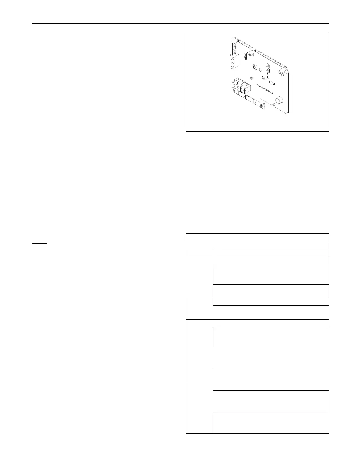
IMO-I5500 3
P/N VC002065
Iso/Readback Board
TABLE 1
Selector Switch Modes
Control Running
Jog
When the control signal is maintained at terminals B and
C (DC voltage) or G and H (AC voltage), the actuator will
2 Wire
drive to the full counter-clockwise position
When the control signal is de-energized, the actuator will
drive to the full clockwise position.
Latch
2 Wire When 2 Wire Mode is selected, the Running Mode must be
set to “Jog”.
Jog
When the control signal is maintained at terminals B and
C (DC voltage) or G and H (AC voltage), the actuator will
drive to the full counter-clockwise position
3 Wire When the control signal is maintained at terminals A and
C (DC voltage) or F and H (AC voltage), the actuator will
drive to the full clockwise position
When the control signal is de-energized, the actuator will
remain in position.
Latch
When a momentary control signal is applied to terminals
B and C (DC voltage) or G and H (AC voltage), the
3 Wire actuator will drive to the full counter-clockwise position
When a momentary control signal is applied to terminals
A and C (DC voltage) or F and H (AC voltage), the
actuator will drive to the full clockwise position.
2. Calibrate the Span position by using the on-board
CCW push button to drive to the full counter-clockwise
position. Adjust the “Set Span”potentiometer until you
read the desired Span signal (20 mA or 10 VDC).
3. If you are using the Position Readback signal in con-
junction with a high or low voltage control signal,
return the selector switch to the “Run” mode.
3a. If you are using the Position Readback signal without the
high or low voltage control signal, leave the selector
switch in the “Man” position.
Figure 1

 Loading...


