3.3 Option “K” – Mechanical Brake
P/N VC099715
The highly efficient hardened steel spur gear system
requires that the brake option be installed on all butterfly
valve and damper applications. It is also recommended on
PVC ball valves and resilient seated valves. The brake will
hold the valve in position against a force as great as the
torque rating of the actuator.The brake option draws 4 watts
and is universal to all standard V-Series actuators.
It is simple to install with a plug-in connector and two philips
head mounting screws.No additional brackets are required.
This option can be installed in the field; order kit
P/N VC099715.
3.4 Option “P” – Feedback Potentiometer
P/N VC099200
The Feedback Potentiometer option provides 0 – 1000 Ohm
resistance feedback and includes a 12 position terminal
block for internal wiring.
This option can be installed in the field; order kit
P/N VC099200.
3.5 Option “S2” – Two Auxiliary Limit
Switches P/N VC099000
The extra switches and stainless steel cams provide dry
contacts and are fully adjustable to trip at any position.
They are often used for position indication or to interlock
other devices (such as in sequencing operations). The
switches are single pole, double throw switches rated for
1/2 HP, 11 amps @ 250 VAC, CSA certified.Auxiliary switch kit
P/N 99000 is universal to all standard V-Series actuators and
includes “flying wiring leads” for termination inside of the
actuator enclosure using the supplied 6 position terminal
block. This option can be installed in the field; order kit
P/N VC099000.
3.6 Option “T” – Heater and Thermostat
P/N VC099515, P/N VC099523
The heater and thermostat option is a self-adhesive, resist-
ance heater strip which is applied to the primary gearbox.
It installs with a plug-in connector and is required in instal-
lations where the ambient temperatures drop below 32˚ F.
The heater option is also recommended in installations that
experience wide temperature swings in order to evaporate
any condensation. Thermostat is pre-set to activate at or
below 40˚F and deactivate at or above 60˚F.The heater draws
15 watts @ 115 VAC; 40 watts @ 230 VAC.This option can be
installed in the field; for 115 VAC applications, order kit
P/N VC099515 and for 230 VAC applications order kit
P/N VC099523
3.7 Option “Y” - Keyed Output
150 – 600 in-lb actuators are supplied with a 3/4" female
square output coupling; when the “Y” option is selected
they are supplied with a 15mm female keyed output.
1000 – 3000 in-lb models are supplied with a 1" female
square output coupling; when the “Y” option is selected
they are supplied with a 20mm female keyed output.
This option is factory installed only.
3.8 Option “Z” – Handwheel Override
All V-Series actuators are supplied with a wrench-operated
manual override shaft.If the Handwheel Override option is
selected the shaft is replaced by a declucthable shaft and
a six-inch handwheel.
This option can also be installed in the field; for 150 – 600
in•lb models order kit P/N VC009097 and for 1000 – 3000
in•lb models order kit P/N VC009098. See (Page 8) for
Handwheel Override reference.
3.9 CSA Certification
CSA Certification is standard on all standard V-Series actua-
tors for applications in either Hazardous (WX) or non-
Hazardous (W) locations. CSA certified actuators are iden-
tified by the CSA logo on the product label.
IMO-I5500 7
Figure 9
Option “S2” – Two Auxiliary Limit Switches
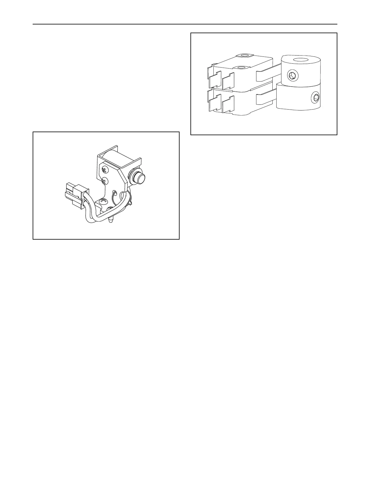
Figure 8
Option “K” – Mechanical Brake
 Loading...


