IMO-I5500 9
4.7 Lubrication
All rotating power train components are permanently
lubricated with multi-purpose Lithium grease suitable for
the operating temperature range of the actuator.
Additional lubrication is not required in normal operation.
4.8 Problem Prevention
Most actuator problems result from improper installation.
• Incorrect Wiring and Set Up Make certain the actuator
is wired correctly and travel stops are properly set
before power is applied.
• Coupling, Alignment, and Mounting Do not add
extra torque! Make certain that the mounting
arrangement is sturdy, centered, properly aligned, and
that all mounting hardware is secure and properly
tightened.
• Moisture Replace the cover tightly and make certain
conduit entry holes are sealed properly to prevent
moisture infiltration.
4.9 Warranty
All V-Series actuators are backed by a 2 year warranty that
covers materials and workmanship.
4.10 Technical Assistance, Replacement
Parts, Options and Repairs
All replacement parts, plug-in options, accessories, and
repair services for V-Series actuators are available through
a network of qualified Metso Stocking Representatives.For
further technical information or to locate the Metso
Automation Stocking Representative closest to you, con-
tact w
ww.metso.com/valvcon.
5 SPECIFICATIONS & TECHNICAL INFORMATION
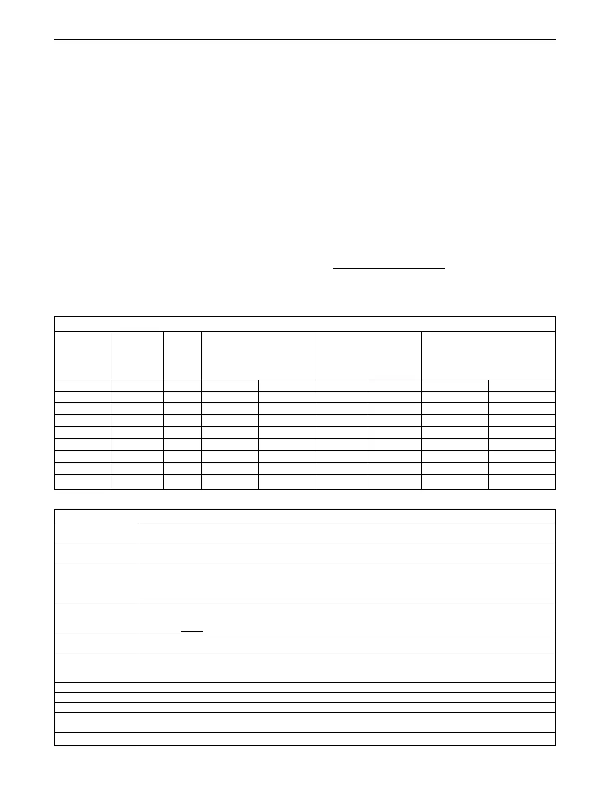
Table 2 - Torque & VA Ratings
Torque @ Speed Duty VA Rating Max Running Max Effective Peak
breakaway (seconds Cycle Current at Full Load Inrush Current (= .66 x)
per 90˚ (True MS) Peak rush
rotation)
115 VAC 230 VAC 115VAC 230 VAC 115 VAC 230 VAC
150 in•lb 8 75% 70 vA 115 vA .6 amps .5 amps 1.25 amps .924 amps
300 in•lb 15 75% 70 vA 115 vA .6 amps .5 amps 1.25 amps .924 amps
600 in•lb 30 75% 70 vA 115 vA .6 amps .5 amps 1.25 amps .924 amps
1000 in•lb 25 75% 92 vA 161 vA .8 amps .7 amps 1.66 amps 1.29 amps
1500 in•lb 40 75% 92 vA 161 vA .8 amps .7 amps 1.66 amps 1.29 amps
2000 in•lb 55 75% 92 vA 161 vA .8 amps .7 amps 1.66 amps 1.29 amps
2500 in•lb 70 75% 92 vA 161 vA .8 amps .7 amps 1.66 amps 1.29 amps
3000 in•lb 75 55% 92 vA 161 vA .8 amps .7 amps 1.66 amps 1.29 amps
Table 3 - Specifications
Temperature Range 32°F to 150°F (without heater and thermostat)
-40°F to 150°F (with heater and thermostat)
Conduit Connections (2) 3/4” NPT in sizes up to 600 in•lb (3/4” to 1/2” reducing bushings included)
(2) 3/4” NPT in sizes 1000 in•lb and above (3/4”to 1/2” reducing bushings included)
Output 150 to 600 in-lbs: ISO 5211 F05 and F07 bolt circles, 3/4" female square (14mm female square w/ "I" Option;
15mm female keyed output w/ "Y" Option).
1000 to 3000 in-lbs: ISO 5211 F07 and F10 bolt circles, 1" female square (1000 in-lbs: 19mm female square w/ "I" Option;
1500 - 3000 in-lbs: 22mm female square w/ "I" Option; 1000 to 3000 in-lbs: 20mm female keyed output w/ "Y" Option)
Duty Cycle The actuator may run continuously at temperatures below 104º F for up to 15 minutes. After that 15 minutes,
the actuators may run up to 75% duty cycle (between each full cycle), the actuator must rest for 1/3 of the 90 degree
cycle time. NOTE: At 50 Hz, the duty cycle is 60% @ 104° F.
Voltage 115 VAC: 103.5 to 126.5 VAC, 50 or 60 Hz
230 VAC: 207 to 253 VAC, 50 or 60 Hz
Limit Switches (2) Single pole, double throw switches rated for 1/2 HP, 11 amps @ 250 VAC, CSA certified, fuse protected.
Two standard switches are used for end of travel control, and for pilot or position indication at terminal 5 and terminal 6.
Indication outputs are protected by 0.25 AMP permanent auto reset polyfuses – reset time approximately 3 mins.
Motor Split phase, capacitor driven motor with Class B or better insulation; sub-fractional horsepower
Lubrication Permanently lubricated gear train and bearings
Gear Train Hardened steel spur gears
Approximate Weight 17 lbs for sizes up to 600 in•lb
31 lbs for sizes 1000 in•lb and above
Enclosure Die cast aluminum

 Loading...


