3.10 Voltage
115 VAC or 230 VAC. V-Series actuators are rated for full
torque at +/- 10% of the nominal voltage at 50 Hz or 60 Hz.
At 50 Hz operation, the duty cycle decreases proportionally
and the cycle time increase.V-Series actuators are rated for
a minimum of 75%* duty cycle @ 60 Hz @ 104˚F.They provide
a 75% duty cycle and are rated for 50 Hz or 60 Hz as a
standard feature.
* 55% duty cycle for 3000 in•lb actuators.
4 GENERAL OPERATING INFORMATION
For enclosure specifications and dimensions, see (Tables
2-3 and Figure 10)
4.1 NEMA Ratings and CSA Certification
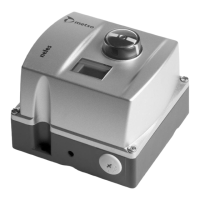
Metso manufactures two styles of V-Series actuator enclo-
sures: the "W" enclosure is weathertight and designed to
NEMA 4/4X standards the "WX" enclosure is "explosion-
proof" and designed to NEMA 4/4X/7&9 (Class 1, Division
1, Groups C and D,Class 2, Division 1, Groups E, F and G and
Class 3) standards.
Actuators are certified by CSA to meet Canadian and U.S.
standards for applications in both Hazardous and Non-
Hazardous locations. The “WX” option must specified at
the time of ordering and can only be installed at the fac-
tory. Ensure that the actuator's ratings are appropriate for
the application environment prior to installation. Use
extreme care when removing the cover. Scratches or nicks
on the flanges may cause the enclosure not to meet NEMA
or CSA specifications.
4.2 Wiring
Metso AC voltage actuators use reversing induction
motors which cause high voltages Devices connected to
terminal 3 and to terminal 4 must be rated for minimum
250 VAC (440 VAC for 230 VAC applications). Controllers
with solid state outputs must be rated for more than 250
VAC. We strongly recommend that relay outputs be used
on connected devices. D
ue to the induction feedback volt-
age, multiple actuators can not be wired in parallel.
Separate (isolated contacts) must be provided for each
actuator. If the actuator is driven by contacts on a PC or
PLC, make sure the contacts have the proper ratings.
4.3 Duty Cycle and Motor Protection
V-Series actuators can operate continuously for up to 15
minutes at 104˚F. After 15 minutes of continuous operation
they are rated for 75% duty cycle operation at 104˚F and for
30 starts per minute. Duty cycles decrease at temperatures
in excess of 104˚F. Duty cycle is the maximum proportion
of “on”time and the minimum required “off” time to prevent
thermal overloading. Actuators with cycle times of 30
seconds must rest at least 10 seconds between cycles.
Higher temperature applications decrease duty cycle.
Metso's AC motors contain thermal overload protection.
Exceeding the rated duty cycle may cause the thermal
overload switch to temporarily remove power to the
motor and cause it to stall. After the motor cools, the actu-
ator will resume normal operation. The thermal protec-
tor is a safety device,designed for infrequent use.Constant
tripping of the thermal overload protector may cause pre-
mature motor failure.
4.4 Operating Temperature Limits
V-Series actuators are designed to operate in ambient
environments between 32˚F and 150˚F. If the ambient
temperature may drop below 32˚F, the heater and thermo-
stat option must be installed.The actuator is rated to operate
at -40˚F with the heater and thermostat option installed. In
outdoor applications where ambient temperatures exceed
80˚F, actuators should be shielded from direct sunlight. In
applications with high media temperatures, insulating
blankets, heat shields and/or extended mounting shafts
should be used to maintain ambient temperatures at the
actuator within normal operating limits.
Heaters and thermostats are required for all outdoor appli-
cations and may also be used to dry condensation in high
humidity environments.
4.5 Actuator Mounting
The actuator may be mounted in any position including
upside-down. It must be firmly secured to a direct mount
flange or sturdy mounting bracket. A minimum of four
bolts with lock washers should be used to secure the
actuator to the bracket. Flexibility in the bracket is not
allowed, and backlash, or "play", in the coupling should be
minimized. The actuator output shaft must be in line
(centered) with the valve shaft to avoid side-loading the
shaft. See (Figure 10) for output drive dimensions and
mounting hardware specifications.
4.6 Manual Override
To use the manual override, push the override shaft down
approximately 1/4 inch to disengage the motor from the
gear train. Failure to disengage motor prior to turning
override will cause damage to the actuator. While holding
the shaft down, turn the shaft with a wrench or handle to the
desired position. The override shaft on actuators below
1000 in•lb must be rotated in the opposite direction of the
desired direction of the output shaft. In actuators 1000
in•lb and above, the override and the output shaft turn in
the same direction.
Do not drive the actuator beyond the limit switch settings;
it is possible to damage installed options such as a feedback
potentiometer. The manual override shaft must be
returned to its fully upward position before the motor is
re-engaged. Rotate the shaft slightly to align the spur gears
until the shaft "springs" back to its re-engaged position.
Note: The rotation direction of the output may not be the
same as the rotation of the override shaft!
8 IMO-I5500

 Loading...
