2 INSTALLATION
2.1 Tools Required
• 1/16” Hex wrench
2.2 Installation Instructions
! Disconnect Power!
1. Remove and discard screw that secures Motor Board
to the upper bracket. (See Figure 6).
2. Remove 5/16”nut and lockwasher from potentiometer
(Pot) shaft and insert, “Pot shaft up” through hole in
upper support bracket. Align lockwasher and nut and
tighten.
3. Plug Pot connector into the 3-pin connector on the
front of the Iso/Readback Board. Plug Iso/Readback
Board into Motor Board (P/N VC002015) via 10-pin
connector and secure with three mounting screws.
4. Place small (20-tooth) gear on Pot shaft and tighten.
Place spacer on Camshaft then place large (48-tooth)
gear on Camshaft. Properly positioned, gears should
mesh evenly.
5. Loosen setscrew in CW or CCW cam. (1/16 hex wrench)
CW = bottom cam
CCW = next cam up from bottom cam
6. Connect AC Power to terminal 1 (Hot) and 2 (Common)
of Motor Board P/N VC002015. Select Manual Mode
and drive to desired STOP position. Remove power.
7. Rotate cam in the direction of travel to the exact point
that the switch “clicks”open. Tighten setscrew
8. Repeat procedure 5, 6 and 7 to set opposite end of
travel limit.
9. Connect AC or DC Control Signals to AC or DC Control
terminals to achieve desired operation, as indicated in
wiring diagrams on previous pages.
IMO-I5500 5
Clockwise (CW) CAM and SWITCH
Counter-Clockwise (CCW) CAM and SWITCH
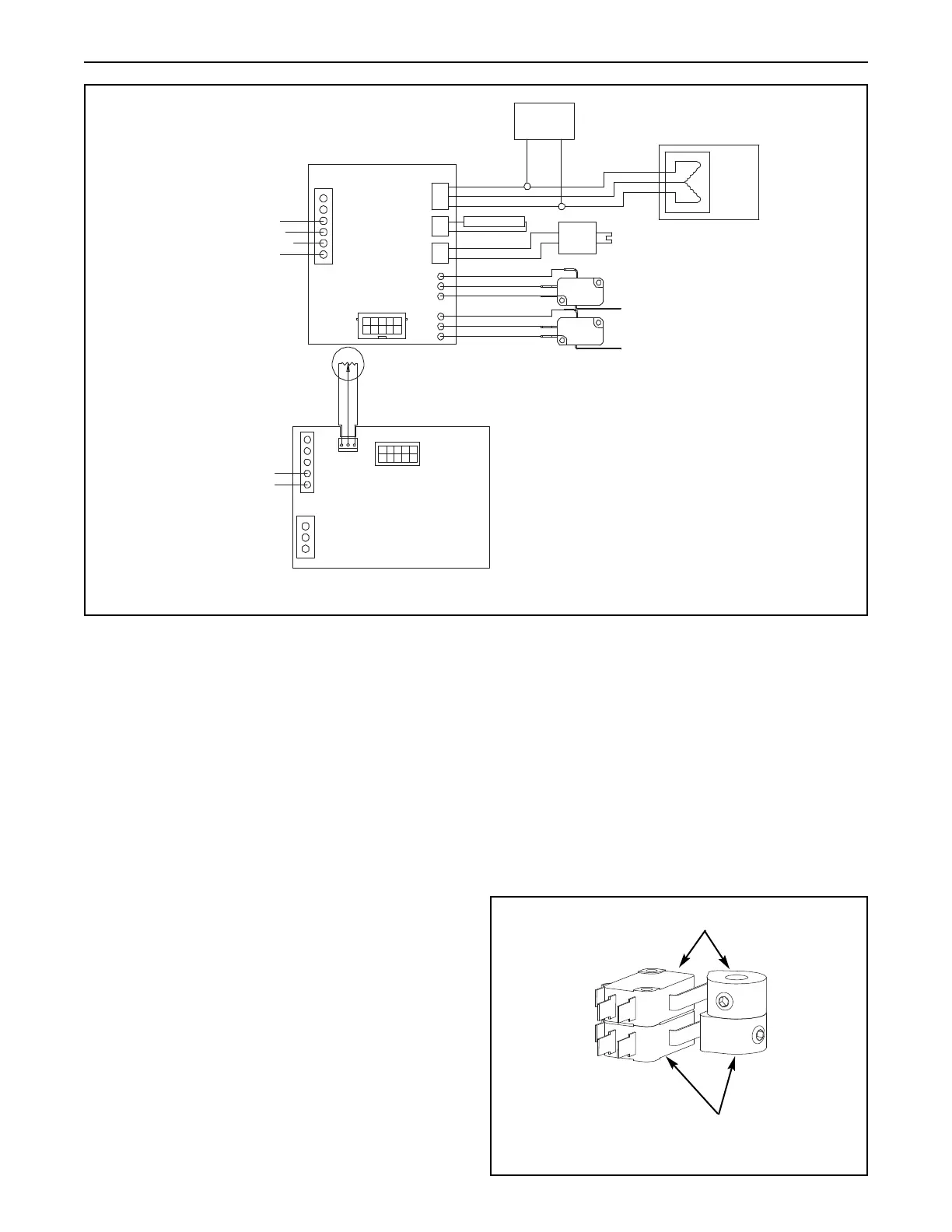
Wiring Diagram – Retransmit Only
P/N VC002065 Iso/Readback Board
CAUTION: MORE THAN ONE LIVE CIRCUIT!
CAUTION: DOUBLE POLE/NEUTRAL FUSING!
Motor Board
Motor
Board
Iso/Readback
Board
TB1
6
5
4
3
2
1
AC COMMON
AC HOT
MOTOR
CONNECTOR
HEATER
OPTION
CONNECTOR
BRAKE
OPTION
CONNECTOR
E10
E11
E12
E13
E14
E15
J4
TO OPTION BOARD
CCW RED
RET BLACK
CW WHITE
HEATER
BROWN
RED
ORANGE
GRAY
VIOLET
BLUE
J2
J3
J1
MOTOR
CAPACITOR
BRAKE SOLENOID
CLOCKWISE (BOTTOM)
LIMIT SWITCH
COUNTER-CLOCKWISE (UPPER)
LIMIT SWITCH
COM
NO
NC
COM
NO
NC
1
2
3
+5V RED
SIG. BLACK
RET. GREEN
TB2
A
B
C
D
E
F
G
H
J3
FROM MOTOR BOARD
TB1
J1
RETRANSMIT+
OUTPUT –
POSITION FEEDBACK POT.
CW HOT
CCW HOT
Terminal 4 CW Hot (Must Connect)
Terminal 3 CCW Hot (Must Connect)
Terminal 2 AC Common (Must Connect)
Terminal 1 AC Hot (Must Connect)
4-20 mA or 0-10 VDC
Retransmit Output
Terminal D POS (+)
Terminal E NEG (–)
Figure 4
Figure 5

 Loading...


