Chapter 3: Installation
Junction Box Wiring
(10/96)
Junction Box
Wiring
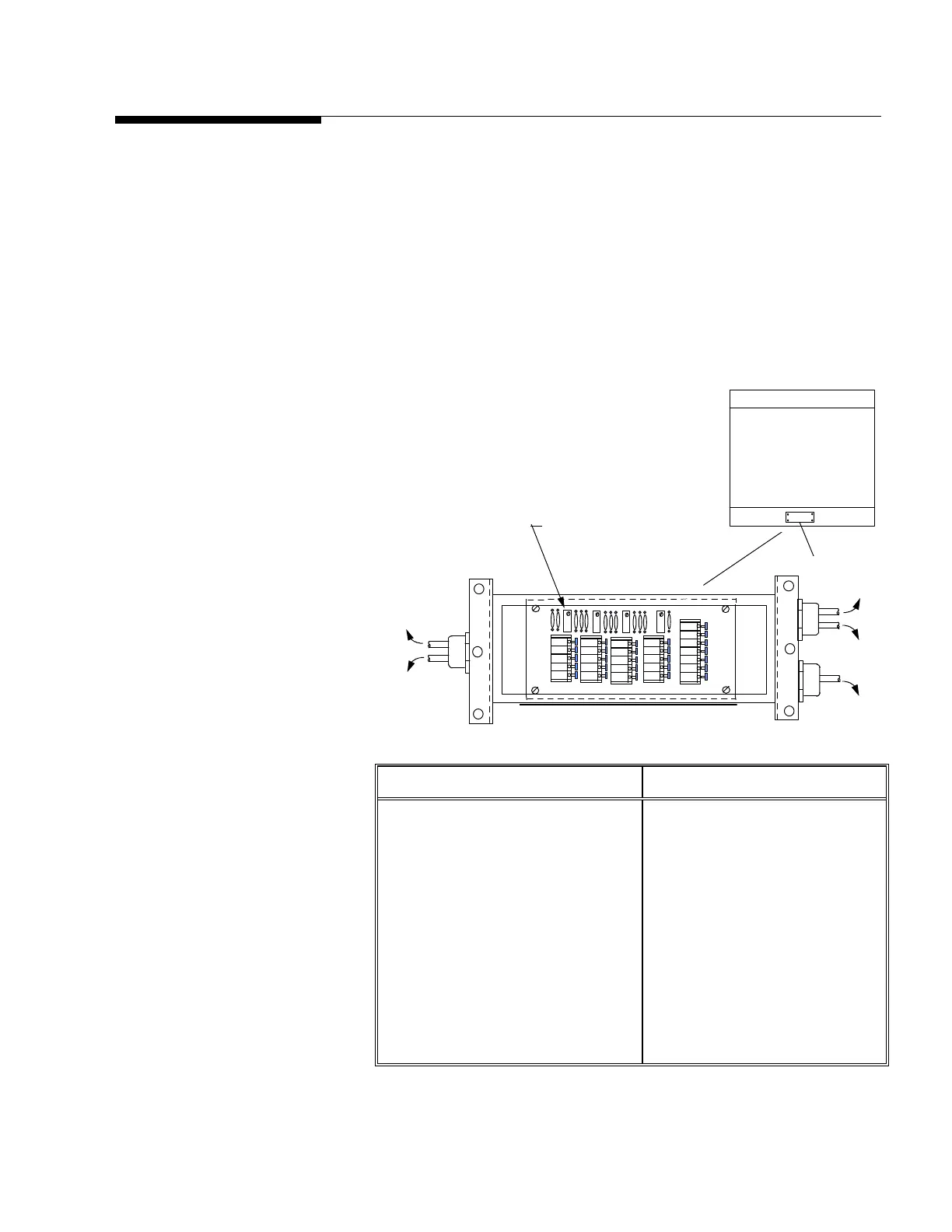
Remove the junction box cover plate from the top of the side rail of the
platform. Thread the instrument cable through the connector on the end
of the junction box and terminate the cable to the terminals provided (see
figure 3-c). After terminating cable check all connections and place
desiccant bag inside junction box. Reinstall junction box cover. Make
sure the rubber gasket is clean and correctly located. Tighten all screws
and check that all cord grip caps are tight.
Load Cell Wiring Instrument Cable Wiring
Function Color Function Color
+ Excitation Green + Excitation White
+ Sense Yellow
+ Signal White + Signal Green
Shield Yellow Shield Orange
– Signal Red – Signal Black
– Sense Red
– Excitation Black – Excitation Blue
(Based on Mettler Toledo
cable number 510624370)
LC 2 LC 4
LC1
LC3
Load Cell Orientation
(Top View of Platform)
J Box Cover
to LC 2
to LC 1
to LC 4
to LC 3
to INDICATOR
Individual Load Cell
Trimming Potentiometer
LC 1
LC 2 LC 3 LC 4
- SIG
+ SIG
- SEN
- EXC
+ SEN
+ EXC
SHLD
- SIG
+ SIG
- EXC
+EXC
SHLD
Figure 3-c: 2888 Analog Junction Box Details and Wiring Codes
Note: Turn all potentiometers fully
clockwise prior to calibration.