Installation (cont.)
12 VDC Electrical Installation
Your MT-3000 will work on either positive or negative
ground 12 volt systems. Route wires away from hot engine
components, moving parts and high tension (spark plugs)
wires. Cut wires to proper length, crimping on appropriate
terminals and secure with plastic ties to prevent rubbing or
pinching.
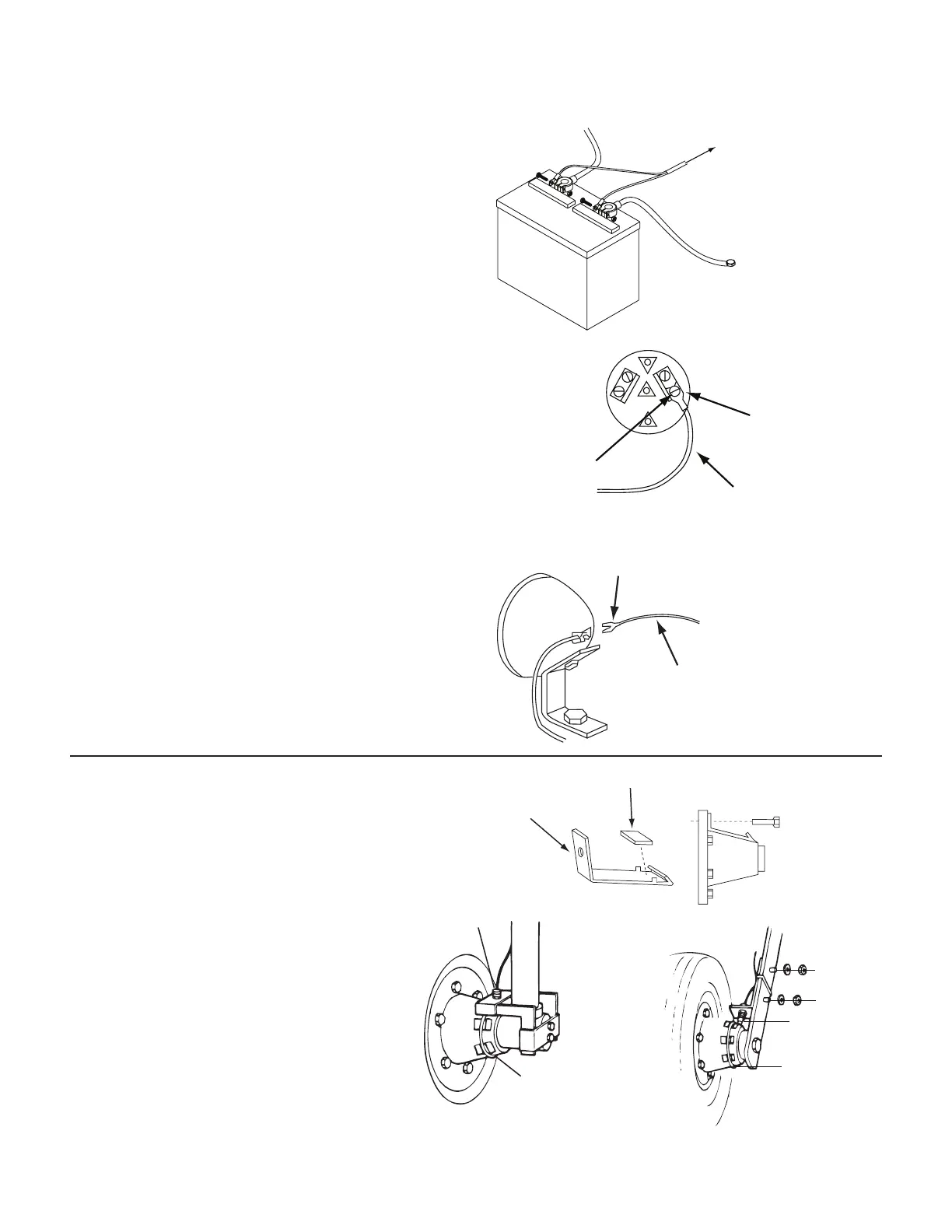
STEP 1
Connect the ORANGE/BLUE jacketed cable to battery
using 5/16” insulated ring terminals. Orange connects to
“HOT” terminal and BLUE to chassis ground terminal. See
Illustration 3.
STEP 2
Connect single ORANGE wire to “ON” terminal of ignition
switch. Use a 12 volt test light to locate terminal which is
“HOT” only when switch is on. (Other possible locations
are hour-meter, fuel, tem or volt gauge.) NOTE: Do not
connect to ignition coil as console damage can result. See
Illustration 4.
NOTE: On dual battery 12 volt systems, all power wires
must be to the same battery. Connect the ORANGE/BLUE
cable (step 1) and then temporarily disconnect the other
battery before testing and connecting the single ORANGE
wire (step 2).
STEP 3
Connect single BROWN wire to lighting circuit. Some
possible locations include light switch, fuse black, headlight
or dash panel light. (This wire is for gauge light only and is
not required for proper operation of console. See Illustration
5.
10
+12VDC
HOT
ORANGE
BLUE
GROUND
(FRAME)
MT-3000
ORANGE/BLUE
Illustration 3
12 VOLTS WITH
SWITCH “ON”
SPADE TERMINAL
ORANGE WIRE
MT-3000
CH
Illustration 4
SPADE TERMINAL
BROWN
MT-3000
LIGHTING CIRCUI
Illustration 5
Magnetic Speed Sensor Installation
The speed sensor has a YELLOW cable tie near the connector
and mates with the main harness cable also having a
YELLOW tie near the connector. Make sure you install the
correct sensor.
Prepare magnet clips as shown. You may also
glue magnets directly to hub using epoxy or
other quality adhesive. Be sure magnets are
evenly spaced at least 2” (5 cm) apart or speed will
not be steady and spray rate will be erratic. We
recommend 1 magnet be installed for each wheel
bolt. Tighten cable ties as shown on next page.
NOTE: If the magnets are closer than 2” (5 CM)
apart their fields may interact causing erratic
operation. Correct this situation by using an even
number of magnets and reversing the polarity
of consecutive magnets. Use a test magnet with one side
marked to check polarity of each installed magnet. On
magnet should attract and the next repel.
DRILL LUG BOLT
HOLE AND BEND
TO FIT HUB.
MAGNET
Cable Tie
Tap thread for
bolts or weld
Speed Sensor
and Bracket
¼” Bolts,
Lockwashers
and Nuts
Speed Sensor
Cable Tie