Installation (cont.)
Plumbing - General
Refer to system diagram on page 6 for component
locations.
NOTE: Before beginning plumbing, make sure you have
the correct system. See Pre-installation section on page
9. Once installed, the servo or flowmeter can not be
exchanged for a different size.
FOR BEST PERFORMANCE AND UNIFORMITY OF SPRAY
1. Minimize use of elbows, tees, nipples, reducers or
anything else that restricts flow.
2. Use pump with enough capacity to handle flow to
nozzles, agitation line and servo valves.
3. Use pressure relief valve set at 60-80 PSI (4 - 5.5 bar)
on positive displacement pumps or centrifugal pumps
capable of more than 6.5 PSI (4.5 bar).
4. Pump output line should be 1” minimum.
16
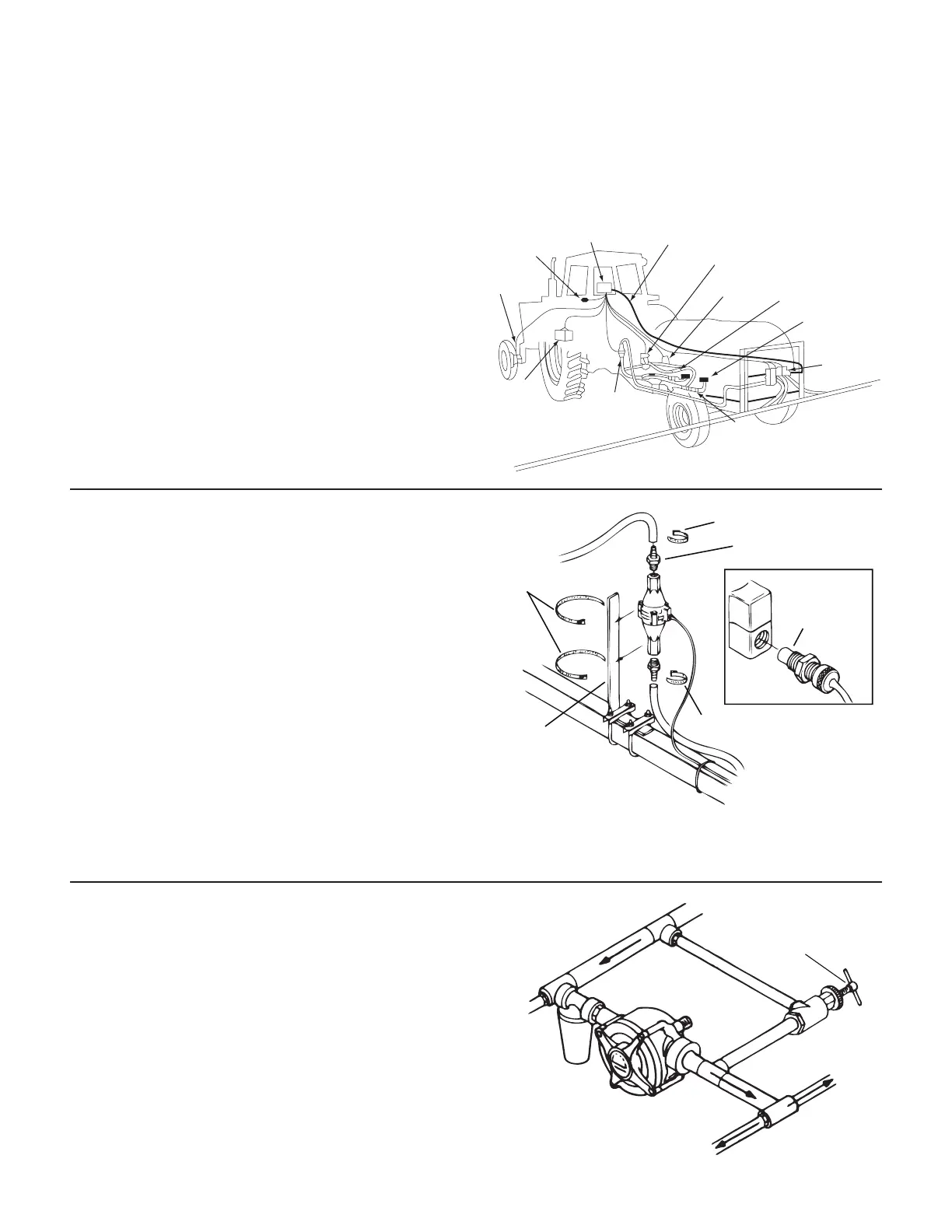
SPEED
SENSOR
IGNITION
SWITCH
MT-3000
PRESSURE TUBING
BOOST SOLENOID VALVE
SERVO
VALVE
BOOST ADJUST
VALVE
AGITATION
INLET
SOLENOID
VALVES
MAIN
SHUT-OFF
FLOWMETER
BATTERY
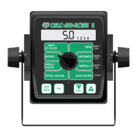
Mounting & Plumbing Flowmeter
1. Flowmeter must be installed at the pump output after
any strainers, return lines or valves. Securely mount
flowmeter (hardware not supplied) in an area away from
intense vibration in a vertical position. The flowmeter
may need periodic cleaning, there fore, it should be
easy to remove. Liquid can flow in either direction but
up is preferred. Make connections using ¾” fittings
without the use of reducers, elbows or sharp bends for a
minimum of 6” (15 cm) either side of the meter.
2. Apply a small amount of grease to the sensor threads and
screw sensor all the way onto hole of flowmeter. The flow
sensor has a GREEN cable tie near the connector which
mates with main harness cable also having a GREEN tie
near the connector. Tighten 3/8” jam nut to lock sensor
in place. Secure cable with plastic ties.
NOTE: Save plastic plugs to protect flowmeter during
storage.
Sprayer Line*
Locknut
Sensor
(green body)
Flowmeter
* NOT SUPPLIED
“L” Bracket*
Hose Clamps*
¾” NPT Male Fitting*
Hose Clamps*
Hose Clamps*
Pressure Relief Valve
If you have a positive displacement pump or a centrifugal
pump capable of more than 65 PSI (4.5 bar) you must install
a pressure relief valve and adjust it to a safe maximum
pressure. NOTE: See Plumbing Guidelines on page 32 for
adjustment procedure. If a positive displacement pump is
operated without a pressure relief valve, damage may result
to pump or other plumbing component.
For positive
displacement pumps
Tee “C”
Tee “A”
Pressure
Relief Valve
5. For pumps rated above 50 GPM (190 lpm), use 1½”
suction line and 1¼” servo valve return line. Plumb
return line into pump inlet or back to tank (not
agitation). Line must have unrestricted flow.
6. Boom having flow greater than 5 GPM (19 lpm) should
use ¾” lines minimum.
NOTE: See Plumbing Guidelines on page 32 for additional
information.