11
Installation (cont.)
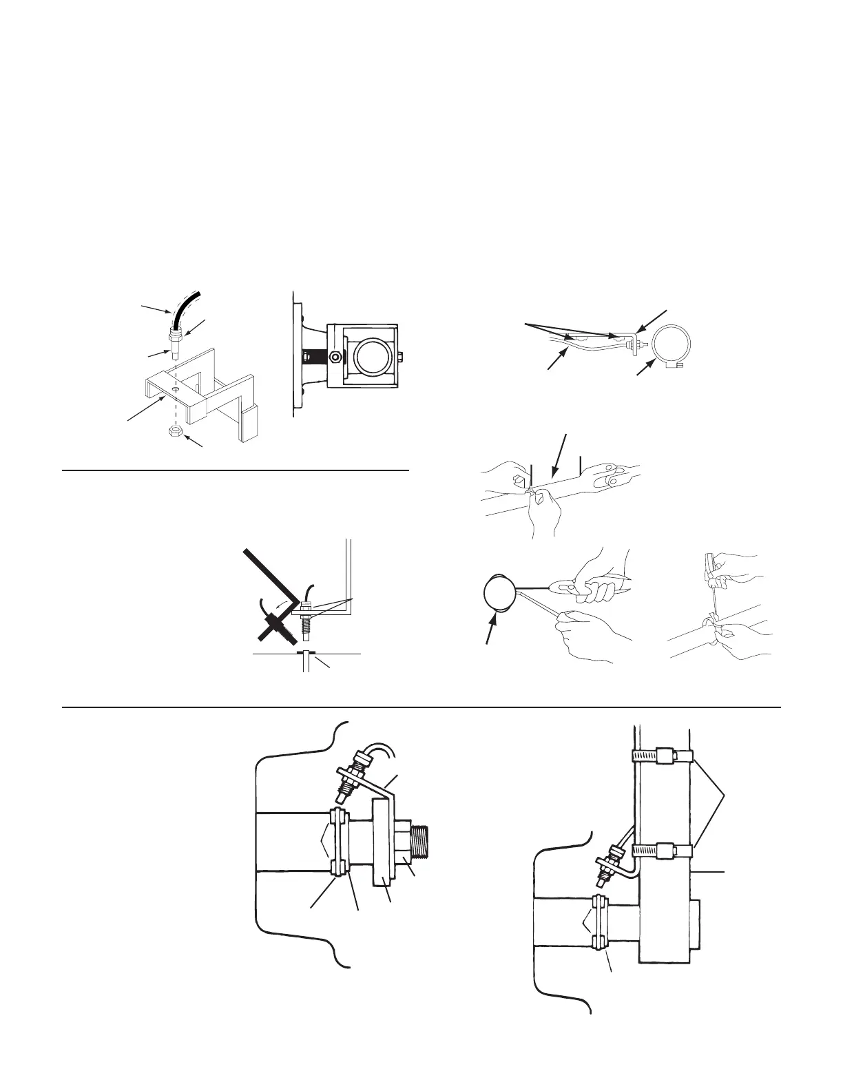
Mounting Bracket
Cut and bend as required. Rigidly mount using ¼” bolts, self-
tapping screws or by welding. NOTE: Always disconnect
console before welding on equipment.
If the “L” bracket will not fit as in the implement wheel
examples, you may fabricate one as shown using a minimum
of materials. Do not attach bracket to the spindle housing
or any other part which does not maintain power alignment
while turning. Bracket must be securely mounted.
Hub
Top View
Sensor
3/8” nut
Optional section
of hose to
protect cable
3/8” nut
3/8” hole
for sensor
DRIVE SHAFT
DRIVE SHAFT
VEHICLE EQUIPMENT FRAME
¼” BOLTS OR
SELF-TAPPING SCREWS
SENSOR CABLE
12” (30 CM) MAXIMUM from U-JOIN
Sensor Adjustment
Unthreaded tip of sensor
must extend beyond
locking nut. Adjust sensor
for approximately ¼” (.6
cm) air gap from tip of
sensor to cable tie of hose
clamp adjusting screw.
Sensor may be angled up
to 45 from perpendicular
but must be directly over
magnets.
45° max
Sensor
(Green body)
3/8” nuts
be rigidly
mounted
be mounted more than
45° from perpendicular
¼” to ½” air gap
Drive Shaft Installation
Use this installation on pickups, 4-wheel-drive tractors,
planters, etc.
Locate sensor mount bracket on frame near transmission,
transfer case or hanger bearing, where drive shaft has
minimum up/down movement.
Secure two (2) magnets on drive shaft (with long dimension
in direction of rotation, exactly opposite each other, and at
least 2” (5 cm) apart using either cable ties or hose clamp
(not provided) as shown. NOTE: If using hose clamp,
position adjusting screw between magnets. Hose clamp
must be non magnetic stainless steel.
USING HOSE CLAMP
ATV Installation
Follow the same basic
procedures as implement
wheel installation but refer to
the following Illustrations for
mounting locations on front
wheel.
CAUTION: Sensor should be
installed on side of wheel
without valve stem to avoid
possible interference.
Sensor Bracket
Axle
Nut
Swing Arm
Hub
Rim
Plastic
Cable
Tie
Magnet
Cut Bracket
to Clear Rim
Cut and Bend
Bracket as
Required
Metal
Hose
Clamps
Fork
Tube
Axle
Hub
Rim
Magnet