Installation (cont.)
General Installation
YOUR SPRAYER
All the components of your sprayer must be sized correctly
and in good working order. Plumbing Guideline on page 32
will give you some suggestions, but the details on proper
plumbing are basically beyond the scope of this manual.
Nozzle manufacturers offer detailed application literature
which includes valuable technical information. The MT-3000
will make a properly designed system perform far better than
any manually operated system. The MT-3000 can not make
a poorly plumbed system perform properly and may cause a
marginal system not to operate at all. You sprayer dealer and
chemical supplier want you to be successful and will assist in
selecting proper equipment.
SPRAYER PLUMBING
Remove all valves and regulators not shown in the system
diagram. See page 8. For ease of use and to maximize the
benefits of your MT-3000, you should replace manual boom
valves with electric solenoid type valves.
WELDING
Unplug the wiring harness from your MT-3000 console
before doing any welding on your equipment.
EXTENSION CABLES
Enough cable is provided for typical sprayer applications
such as pickups, high-boys, 3 point hitch, etc. If you need
more length 5’, 10’, 15’ and 20’ extensions are available.
TIPS ARE THE KEY
Many sprayers today are operating with wrong size, worn,
damages, clogged or improperly installed spraying tips.
Make sure your tips are correct and in good condition.
CAUTION: Never put chemicals in your sprayer until it has
been completely checked out with water to verify proper
operation.
9
Mounting the Display Console
Select a mounting location which seems most workable,
and best fits your needs. It should be convenient to reach
and highly visible to the operator. DO NOT INSTALL IN
A POSITION THAT OBSTRUCTS THE VIEW OF THE ROAD
OR WORK AREA. Whenever possible, avoid locations that
expose the console to direct sunlight, high temperature,
strong chemicals or rain.
NOTE: Route wiring harness away from sharp edges, heat,
moving parts or area of operator movement. Allow enough
slack at hitch connections for turning.
Make a ground wire using an 8” (20cm) length of 14 GA.
BLUE wire. Crimp a female tab terminal on one end and a
¼” ring terminal on the other end.
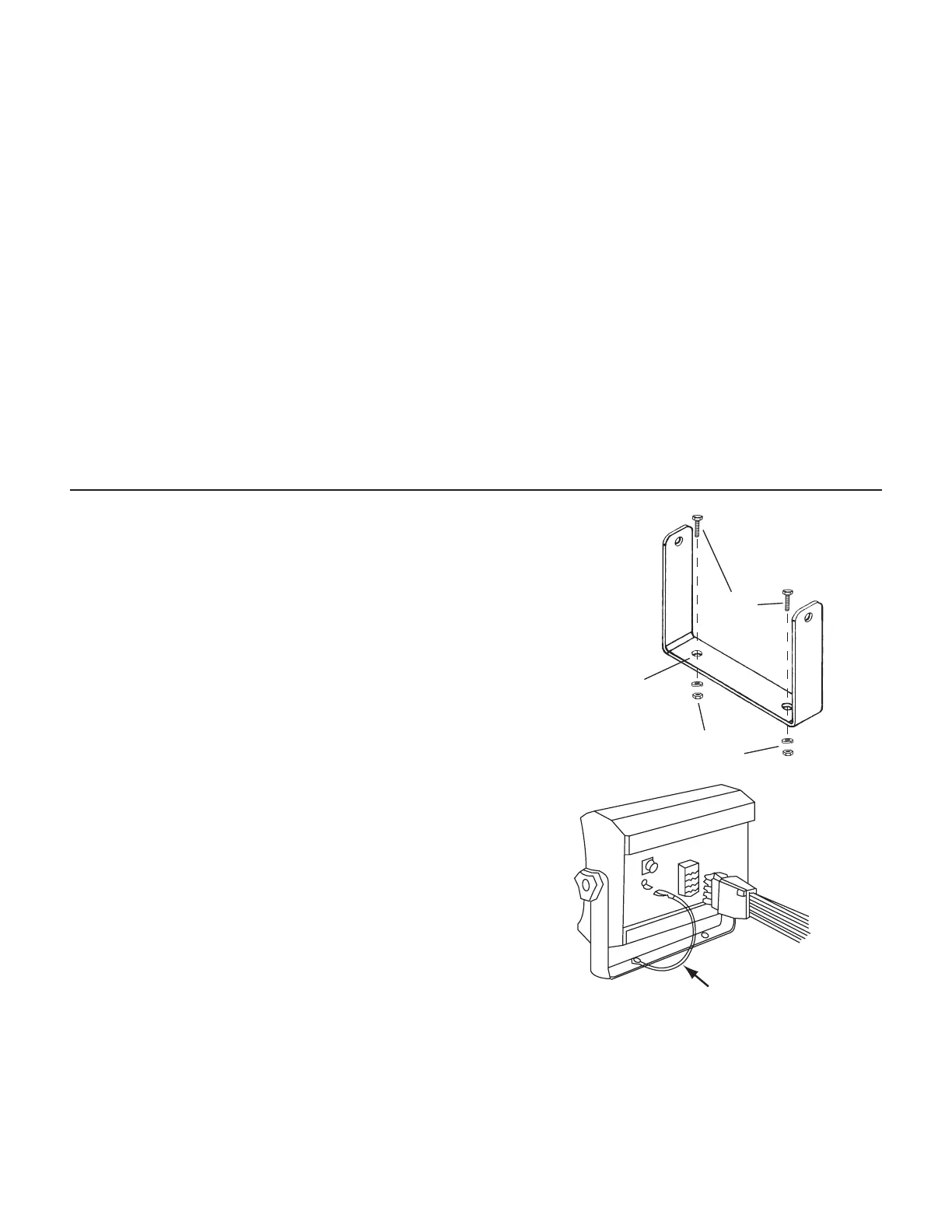
Mount console bracket and one end of ground wire on a
flat rigid surface using the ¼” bolts or self-tapping screws
provided. See Illustration 1.
Insert mounting knob through “U” bracket and rubber
washer. Rubber washer will hold knob in place while
installing the console. Insert console and secure with
adjusting knobs. Connect ground wire terminal on console.
See Illustration 2.
Drill ¼” (7mm)
holes for bolts,
or 3/16“ (5mm)
holes for self-
tapping screws.
Bolts
Lockwashers
and nuts
Illustration 1
GROUND WIRE
Illustration 2