17
Installation (cont.)
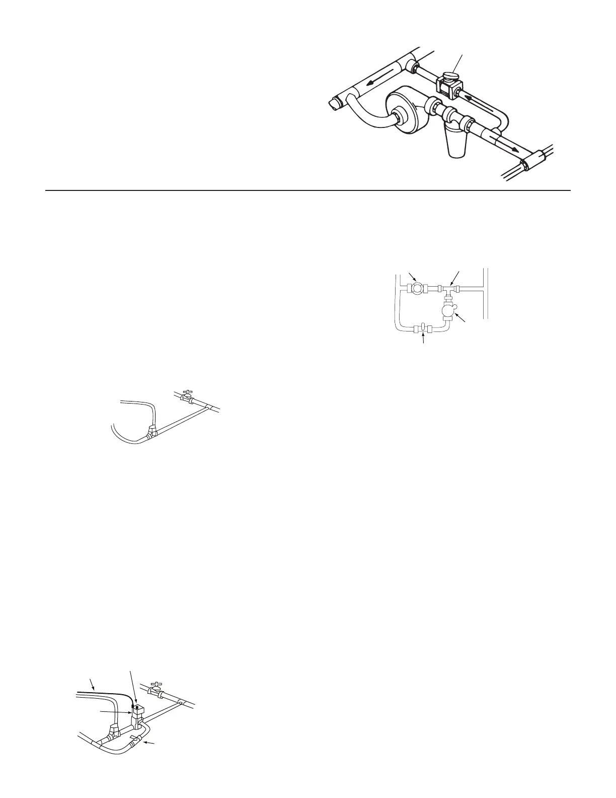
Range Adjust Valve
With over-sized pumps it may be necessary to install a range
adjust valve. The range adjust valve will make your pump
appear smaller to the rest of the system. Adjustment of this
valve is covered in the Pre-Field checkout on page 21.
Tee “C”
Adjust Valve
Tee “A”
For oversized pumps
Servo, Throttling & Boost Valves
Although installing boost valve does involve additional
expense, it offers instant flow response and assures sufficient
by-pass by automatically opening when a boom is shut off.
1. When Servo and throttling valves are installed without
boost solenoid the outlet of the servo valve must be
connected directly to the pump inlet or into the tank
with no restrictions. Connection to the agitation line will
probably cause slow response and marginal operation.
Connect the 5’ (1.5 m) servo cable (reverse connector
and orange boost valve wire) to the servo.
NOTE: If boost valve is not used, tape off orange with to
prevent shorting to frame. (If this wire shorts to frame
ground, the internal circuit breaker will trip, turning booms
off and stopping acre count.)
NOTE: The servo may connect directly to the servo lead on
the main harness (reversed connector). If more length is
needed use the 5” (1.5 m) servo cable.
2. Use this plumbing diagram if your boost valve has flo-
thru port. Crimp 1 female tab terminal onto ORANGE
wire of servo valve cable (reversed connector.) Slip it
on boost solenoid terminal. Cut a length of 14 Ga. BLUE
hook-up wire and crimp a female tab terminal on one
end and a ¼” ring terminal on the other. Ground other
solenoid terminal using this wire.
SERVO
VALVE
“T” FITTING
BOOST ADJUST
BOOST
SOLENOID
VALVE WITHOUT
BOOST SOLENOID
SERVO
VALVE
CABLE
FROM PUMP
THROTTLE
VALVE
SERVO
RETURN
TO BOOMS
BOOST
SOLENOID
BOOST
ADJUST
ORANGE
CONNECT TO
FRAME GROUND
SERVO AND THROTTLE
VALVE WITH
BOOST SOLENOID
WARNING: Do not use the MT-3000 pressure gauge for
toxic chemicals or materials in compatible with nylon,
EPDM, brass, tin/lead solder or phosphor bronze (such as
liquid fertilizer). Use a suitable gauge mounted in a safe
location or install a gauge protection (diaphragm).
Three fittings are provided for the pressure line: a female
elbow, a male connector and a union for quick connection
at the hitch. The fittings have pre-installed “O” rings which
should be replaced with the 4 EPDM “O” rings supplied. Also
supplied is a small snubber washer to be installed in the
male connector. (The snubber washer allows pressure, not
volume, to get to the pressure gauge. Should the tube break
it will seep slowly rather than spray vigorously.
3. If your boost valve does not have flo-thru port, you must
add a “T” fitting.
NOTE: To assure a good connection and avoid corrosion,
coat servo and solenoid lugs with silicone grease.
Ground “Jumper” Installation
If you are spraying with a drawn implement, you must
attach a ground wire “jumper” to complete the electrical
circuit across the hitch for the solenoid valves. One end is
connected to sprayer hitch, the other to your tractor frame.
Cut 2 appropriate lengths of 14 Ga. BLUE wire.. Crimp a ¼”
ring terminal to one of each. Crimp a male tab terminal on
the other end of one wire and a female tab terminal to the
other wire,
Using ¼” bolts, attach one wire to implement frame and the
other to the tractor. Plug the male and female tab terminals
together. Always apply silicone grease to exposed or partially
exposed electrical connections to prevent corrosion.